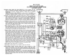
BUICK MODELS 116, 121 AND 129 (1929) DELCO-REMY GENERATING, STARTING SYSTEM DELCO-REMY IGNITION BATTERY :—Exide (Model 116), Type 3-MXV-13-1, 6 volt, 13 plates. The neg- ative (—) terminal is grounded. Starting capacity (20 minute rate) is 114 amperes for 20 minutes. Lighting capacity (5 ampere rate) is 5 amperes for 20 hours, (Models 121 and 129), Type 3-MVX-15-1, 6 volt, 15 plates. The negative (—) terminal is grounded. Starting capacity (20 minute rate) is 133 amperes for 20 minutes. Lighting capacity (5 ampere rate) is 5 amperes for 24 hours. IGNITION:—Coil Model 528-H. Distributor Model 640-J. Breaker contacts sep- arate .018-.024 inch with breaker arm on lobe of cam. Resurface contacts with a fine flat contact file or on a medium hard oilstone. Breaker arm spring tension is 17-21 ounces. Distributor is semi-automatic. Manual ad- vance is 24 degrees (engine). Automatic advance begins at 500 R.P.M. Maximum automatic advance is 26 degrees reached at 2400 R.P.M. (engine). c DISTRIBUTOR Am i) Mounting:—Coil is mounted on the engine case in front of generator. Dis- tributor is mounted in a well on the commutator end of the generator. To remove distributor, disconnect primary lead and manual advance rod. Re- move head with high tension cables intact. Remove advance arm stop screw and lift distributor from place. Viling:—Distributor shaft is oiled from the gear case. Oil gears with Zerk gun through connection on side of gear compartment every 500 miles. Re- move the distributor head and rotor and put 4 or 5 drops of light oil in the wick oiler in the center of the shaft and put a small bit of vaseline on the face of the breaker cam every 2000 miles. re) nw» ce, ass Sey RSL ea > a ©): i 4 ip ~~– 4S fr oe oe Senue ole / GENERATOR ff’ Z- LIGHTING SWITCH fi BREAKER ¢ © CONDEN. oN no 2 oerr ty Ss Timing:—Breaker contacts begin to separate when the piston entering power stroke reaches a position 15 degrees (Model 116) and 17 degrees (Models 121 and 129) before top dead center (measured on the flywheel) with the manual advance lever fully advanced. To set timing, crank engine over until piston No. 1 enters compression stroke. This is the up stroke with both valves closed. Fully advance spark lever. Remove cover over peephole in crankcase over flywheel, on right side of engine, and continue to crank engine until the flywheel mark is directly opposite the line on the edge of the hole. The rotor must be opposite the segment connected to the spark plug in cylinder No. 1 (see diagram). If it is not, remove manual advance AMMETER CIGAR LIGHTER / CIRCUIT BREAKERE , COANCIDENTAL IGNITION i I ‘ { – ‘ 1 } ¥ . i? ©, . 4 4S F o ) 7 \ . / ca), LJ y. 4 Go VALVE TIMING:—INLET VALVES:—Model 116.) stop screw and lift distributor to disengage gears. Then rotate rotor and shaft until rotor is directly opposite proper segment, remesh gears and re- place stop screw. Then loosen the advance arm clamp screw and rotate distributor housing until contacts begin to separate. Connect the segment opposite the rotor to spark plug in cylinder No. 1 and connect remaining plugs in order 4-2-6-3-5 clockwise around the distributor head. Firing Order:—The firing order is 1-4-2-6-3-5. Spark Plugs:—Spark plugs are A.C. Metric. Gaps are .025 inch. Head diameter is 1 9/16 inches; stem diameter is % inch. Tappet clearance is .008 inch (hot). Valve lift is 21/64 inch. Spring pressure is 44-56 pounds closed and 125-141 pounds open. Inlet valves open at 2 degrees after top dead center and close at 42 degrees after lower dead center. EXHAUST VALVES:—Head diameter is 1 9/16 inches; stem diameter is 3% inch. Tappet clearance is .008 inch (hot). Valve lift is 21/64 inch. Spring pressure is 44-56 pounds closed and 125-141 pounds open. Exhaust valves open at 50 degrees before lower dead center and close at 20 degrees after top dead center. g 4 oe ee; Lad — ~~ > Switch [fe TAIL UGHT. SIDE LICHT Ry 1003 BUICK MODELS 116, 121 AND 129 (1929) DELCO-REMY GENERATING, STARTING SYSTEM DELCO-REMY IGNITION INLET VALVES:—(Models 121 and 129.) Head diameter is 1% inches; stem diameter is % inch. Tappet clearance is .008 inch (hot). Valve lift is 21/64 inch. Spring pressure is 44-56 pounds closed and 125-141 pounds open. Inlet valves open at 20 degrees and 4 minutes after top dead center and close 524 degrees after lower dead center. EXHAUST VALVES:—Head diameter is 1 9/16 inches; stem diameter is % inch. Tappet clearance is .008 inch (hot). Valve lift is 21/64 inch. Spring pressure is 44-56 pounds closed and 125-141 pounds open. Exhaust valves open at 50 degrees before lower dead center and close at 20 degrees after degrees and 4 minutes after top dead center. Valve stem guides are re- movable. STARTER:—Model 725-D. Starter is connected to the engine through a me- chanical gear shift. The direction of rotation is counter-clockwise, looking at the commutator end. Starter brush spring tension is 142-134 pounds. Starter Data Torque R.P.M Volts Amperes UB G5 9 ee er A GOO as scieSoeseconareceac < A Re ee LO 60 AGS) S05 voeecutcocnesesetaas LICK secs ccesieassicbseacestieed es irae eReemeeteaes Ae 600 Mounting :—Starter is flange mounted at the right of the engine on the for- and cable. Remove flange mounting screws and pull starter forward. Lift unit from place. Oiling:—Put 8 or 10 drops of light engine oil in the oiler on the commutator end of the starter every 1000 miles. The drive end bearings are oilless. They require no attention. GENERATOR:—Model 940-M. The direction of rotation is counter-clockwise, looking at the commutator end. Generator current regulation is by third brush shunt field and thermostat. Thermostat contacts open at 165 de- grees F. cutting the resistance across the thermostat contacts in series with the shunt field and reducing the output approximately 40%. To adjust gen- erator output, remove commutator cover band and loosen the small round- headed screw on the end plate. Then shift the third brush in a counter- clockwise direction to increase’ the charging rate and in the opposite di- rection to decrease the charging rate. Tighten the screw after making the adjustment. Generator Data Cold Test Hot Test Amperes Volts R.P.M. Amperes Volts R.P.M. 18-20.2...4...2.. BBS BD ic cvcecsscenses 1950 co > 7.35-7.68 0… 1800-2000 Generator motoring, draws 5.5-6 amperes at 6 volts. Shunt field current is 4-6.1 amperes at 6 volts. Brush spring tension is 22-26 ounces. Mounting:—Generator is mounted at the right of the engine on the timing gear case. To remove generator, disconnect lead and water pump. Remove the distributor. Remove mounting screws and pull generator to the rear and out. Oiling:—Put 8 or 10 drops of light oil in the oiler on the commutator end of the generator every 500 miles, The drive end bearing is oiled by splash from the timing gear case. RELAY:—Model 265-B. Relay is mounted on the generator. Relay contacts close at approximately 8 miles per hour when the generator voltage reaches 6.75-7.5 volts and open with a discharge current of 0-2.5 amperes. Charging current at closing of contacts must not exceed 3 amperes. Relay contacts separate .015-.025 inch. Air gap is .014-.021 inch with contacts closed. LiIGHTING:—Switch Model 484-A. Lighting switch is mounted at the base of the steering column. Head lights are 6-8 volt, 21-21 cp. (double filament- double contact) Mazda 1110. Side, dash, tail and corner lights are 6-8 volt, 3 cp. S.C. Mazda 63. Dome light is 6-8 volt, 6 cp. S.C. Mazda 81. Stop and backing iight is 15 cp. S.C. Mazda 87. CIRCUIT BREAKER:—Model 410-D. A vibrating circuit breaker is mounted on the back of the dash. It begins to operate with a current of 25-30 amperes and continues to vibrate limiting the current to 10-15 amperes until the short circuit is repaired.