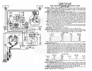
CHRYSLER MODEL G (70) (1926) @/ <= REMY GENERATING, STARTING AND LIGHTING SYSTEM (9) R BATTERY.—Willard, e CRR-15. 6 volt, 105 ampere hour. Starting ge is 125 amperes for 5 minutes. Lighting capacity is 5 amperes for 20 hours. The — pees cP terminal is groun a “Type CWR-15 is used on the Coach. The electrical characteristics are the sa - IGNITION.—Coil Model 284-A. Distributor Lar 656-B. Breaker contacts separate ios .022 inch. Resurface contacts with a fine, flat jeweler’s file or on a medium hard a oilstone. Double contacts are used. They must be gy ecient Set stationary con- 5) ee tacts to open .022 inch with the breaker arm on high point of the cam. Then - RN loosen screw holding mounting plate on which other contacts are mounted and shift until breaker arm is also on the high point of or cam. Adjust breaker gap \ pen careful to keep it within the limits of .018-.024 inch. The tension of the breaker arm spring should be 17.5-20.5 ounces. Distributor is equipped with both ‘ manual and automatic advance. Manual advance is 25°. Automatic advance is 15°. ! Oiling. —Fill the grease cup under the distributor head with medium cup grease and / turn down two turns every two weeks or each geet miles. Place a small bit of vase- line on the face of the breaker cam every 500 miles. Timing.—Breaker contacts begin to separate when the piston entering power stroke 5S Sa reaches a position .100 inch before top dead center with the manual advance ye SF ats A shed lever in the fully advanced position. (5) Firing ee —The firing order is 1-5-3-6-2-4. u Spark Plugs.—Spark plug diameters are 7% inch. a are .027-.030 inch. lj — STARTER. pa 724-C. Starter is connected to the engine through a Bendix drive. oT | c SIDE LIGHT e direction of rotation is counter-clockwise, looking at the commutator end Starter cranks the engine at 144 R.P.M. taking 157 amperes at 5.27 volts. FUSE BLOCK Starter Data hy Torque R.P.M. Volts Amperes / ma Torque R.P.M. Volts Amperes | 70 Inv > nN Ss > S s S ty — °o > 5 TG ene OF AE: Cs a le Se 5 600 Oiling.—Put 4 or z eh ge of light engine oil in the starter bearing oiler every month : or each 10! (Ia) GENERATOR. — Model 941-C. The direction of rotation is counter-clockwise, looking urdicrite AnD venrfiondiivtw) IN OOME LAP at the commutator end. Generator current regulation is by the third brush system cuter ile combined with a thermostat. Thermostat contacts open at 165° F. cutting a_re- eS sistance into the shunt field circuit and reducing the output approximately 50%. t .- |b» To adjust the charging rate loosen the small round headed screw on the generator SWITCH end plate and shift the third brush mophns aes Shift the third brush in a counter-clockwise direction to increase the charging rate and in the o nom direction to decrease the charging rate. Tighten the screw after making the ad- justment. Shunt field current is 5 amperes at 6 volts. Generator brush tension should be 22-28 ounces. SIGNAL SWITCH STARTING SWITCH AMMETER Generator Data 3 Cold Test * Hot Test : Amperes Volts RPM. Amperes Volts RP.M. 5 DO evesuesseatrias oe sesatosesnatates 675 : y Seine Site e050 2 Fis Peete raopeeerret 1900 E ae ale Se aSgs ae eae + a , i ng.—Put 4 or 5 drops of light engine oil in each of the generator bearing oilers (We) bd every month or each | miles. : RELAY. Fi 265-B. Relay is mounted on top of the generator. Relay contacts close at 675 R.P.M. of the generator armature when the voltage reaches 7.2 volts and open oe a discharge current of 0-3 amperes. Contacts separate .020 inch. Air gap between relay armature and coil core is .016 inch, contacts closed. LIGHTING.—Switch Model 475-P. Head and stop lamps are 6-8 volt, 21 cp. S. C. Dash, tail, side and dome lamps are 6-8 volt, 3 cp. S. C. FUSES —Lighting fuses are 10 amperes.