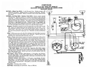
CHRYSLER MODEL 50 (1927) SERIAL NOS. FWOOH UP DELCO-REMY GENERATING, STARTING AND LIGHTING SYSTEM DELCO-REMY IGNITION BATTERY:—Willard, Type WR-13. 6 volt, 84 ampere hour. Starting capacity 15 98 amperes for 20 minutes. Lighting capacity is 5 amperes for 16.6 hours. The posi- @ L@/ os +) prerntna! is grounded, Battery is mounted at left of frame under the front = oor board. IGNITION :—Coil Model 525-E. Distributor Model 638-B. Breaker contacts separate RELAY .018-.023 inch. Resurface contacts on a medium hard oilstone or with a fine flat Ae ees —-} | contact file. To adjust contact opening, loosen lock screw located behind stationary contact and turn eccentric adjusting screw on crescent shaped contact mounting arm until desired breaker gap is obtained. Then tighten lock screw to hold adjustment. O —, we es O Ped Distributor is of the semi-automatic type. Manual advance is 22°. Automatic ad- vance begins at 400 R.P.M. and reaches a maximum of 18° at 1800 R.P.M. The breaker arm spring tension should be 15-20 ounces. Ignition current is 2 amperes at 6 volts with engine running, and 5 amperes at 6 volts with engine stopped. CONDENSER Mounting :—Distributor is mounted at front of engine and is accessible from the right side. Drive is by slotted tongue from the forward end of the cam shaft. To re- move distributor, disconnect breaker lead and high tension cables or remove dis- tributor head. Then remove two mounting bolts holding distributor bracket and ad case to forward end of engine gear case. Distributor can then be lifted from place. Oiling :—Fill the grease cup on the side of the distributor shaft with medium cup grease and turn down two turns every month or each 1000 miles. Keep the oiler on the distributor gear compartment filled with light engine oil. Timing :—Breaker contacts begin to separate when piston entering power stroke reaches a position .063 inches before top dead center with the manual spark control lever in the fully advanced position. To set timing, crank engine until piston No. | enters compression stroke (the up-stroke with both valves closed). Then continue to crank engine until piston No. 1 and No. 4 reach a position .063 inch before top dead cen- ter. Make certain that the spark control lever is in the fully advanced position. Loosen the clamp screw holding distributor in position on spark control lever and rotate distributor until contacts begin to separate. Tighten the clamp screw and replace the rotor and distributor head. Make certain that the rotor is opposite the segment connected to the spark plug in cylinder No. 1. “Red Head” Engines. On cars with high compression ‘Red Head’ engines breaker contacts begin to separate with the piston .004 inch before top dead center with full advance. Allowable variation is .002 inch with piston limits .002 or .006 inch before top dead center. Special spark plugs and special material valves are used in “Red Pread’ engines. ¥’ Valve Timing: —INLET VALVES:—Head diameter, 1 7/16 inches; stem diameter, STARTING SWITCH 3% inch; stem length, 5 1/16 inches; tappet clearance, .004 inch (hot); spring pressure, 35-42 pounds; valve lift, 9/32 inch; intake opens at top dead center and closes at 40° past lower dead center. EXHAUST VALVES:—Head diameter, 1 7/16 inches; stem diameter, 34 inch; stem length, 5 1/16 inches; tappet clearance, .006 inch (hot); spring pressure, 35-42 pounds; valve lift, 9/32 inch; exhaust opens at 48° before lower dead center and closes 2° past top dead center. Stem guides are removable. No oversize valve stems are made. Firing Order: —The firing order is 1-3-4-2. Spark Plugs:—Spark plugs are 74-18 S.A.E. Gaps are .030 inch. = CLOSED CARS. PARKING LIGHT = OP EN CARS. COWL LAMP = CY es€od CARS COWL LAMP FS) | PARKING LIGHT -oPaN CARS. S) “tt | SWITCH DOME LAMP Lee) DASH LAMP AY | 13) DIMMER RESISTANCE TAIL LIGHT i |. é CHRYSLER MODEL 50 (1927) SERIAL NOS. FWOOH UP DELCO-REMY GENERATING, STARTING AND LIGHTING SYSTEM DELCO-REMY IGNITION STARTER :— Model 712-F. Starter is connected to the engine through an outboard Bendix drive Type R-11-X. The direction of rotation is counter-clockwise looking at the commutator end. Starter cranks the engine at 150 R.P.M. taking 150 am- peres at 5 volts. Starter switch is Model 404-V. Starter brush tension is 24-28 ounces. Starter Data Torque R.P.M. Volts Amperes Ollb: ft… en! DOO ae etree sees: 5 6s coe, 70 EGm ne see 15002. = 5D. safle vahcrepore Me 150 30) AO) Reva D250 Fore ec ence 50 fifo eee 200 ! ns 8000. Tite ee 4.7L /…..@…. tet 250 60) eee 55 Oboe Ree reese AA Le Oy 300 O44 ees rai lee ee, a B, 1508 ee eee AD. MMe Lov 400 TQ | gf exe et Locks teccuts ey cy Sie.“ ae 450 Mounting :—Starter is flange mounted at left of engine on forward side of bell housing. To remove starter, disconnect starter cable and remove two flange mounting screws. Then slide starter from place. Oiling :—Put 4 or 5 drops of light engine oil in the oiler on the commutator end of the starter every month or each 1000 m