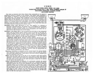
CORD FRONT WHEEL DRIVE—MODEL L-29 (1929) PRODUCTION STARTED JULY 1, 1929. SERIAL NUMBERS 2,925,001 UP DELCO-REMY GENERATING, STARTING SYSTEM DELCO-REMY IGNITION The Cord as America’s first Front Wheel Drive automobile to be placed in production involves a number of new features. The engine, while essentially a stock engine, is reversed in the chassis with the flywheel and transmission at the forward end. The timing chain is likewise at the forward end between the engine block and the flywheel. The crankshaft revolves counter-clockwise. The starter drives to the flywheel and is mounted on the rear of the flywheel case which is thus the forward end of the engine. The battery is mounted near the starter on a bracket above the transmission case under the engine hood. The electrical units are similar to those used on ordinary rear wheel drive cars and no trouble should be experienced in service work. BATTERY :—U.S.L. Type XY-15-X-6, 6 volt. The positive (+) terminal is grounded. Starting capacity (20 minute rate) is 119 amperes for 20 minutes. Lighting capacity (5 ampere rate) is 5 amperes for 21 hours. Battery is mounted on special bracket directly above transmission case under the en- gine hood at the forward end of the engine. IGNITION :—Coil Model 526-¥. Coil is mounted on the back of the instrument board with the ignition switch (which is built in the base of the coil) ex- tending through to the face of the instrument panel. An extra terminal is located on the end of the coil from which the feed for the gasoline and oil gauge is taken. Ignition current is .6-3.0 amperes at 6 volts with engine running and 5 amperes at 6 volts with engine stopped. Distributor Model 658-W. Breaker contacts separate .018-.024 inch. Set contact gap by loosening lock screw on stationary contact mounting plate and turning eccentric adjusting screw until correct gap is secured with breaker arm on lobe of cam. Resurface contacts when necessary with a fine flat contact file or on a medium hard oilstone. Breaker arm spring tension is 18-21 ounces. Distributor is semi-automatic. Maximum manual advance is 15 degrees (engine). Automatic advance begins at 800 R.P.M. of engine. Maximum automatic advance is 13-17 degrees reached at 3600 R.P.M. Dis- tributor has two sets of contacts on a four sided cam. Contacts separate alternately at intervals of 45 degrees corresponding to the firing interval of 90 degrees on the engine crankshaft. Contacts must be synchronized for correct ignition performance. See Timing. Mounting:—Distributor is mounted on the cylinder head. To remove distrib- utor, disconnect manual control rod and primary lead and take off distrib- utor head with cables intact. Then remove hold-down screw in advance arm and lift distributor from place. Oiling:—Fill the grease cup on the side of the distributor shaft with medium cup grease and turn down one half turn every month or each 1000 miles of operation. At the same time remove the distributor head and rotor and oil the wick oiler in the center of the shaft and place a small bit of vaseline on the face of the breaker cam. Timing:—Synchronization of Contacts:—To synchronize contacts use special Delco-Remy Tool and follow directions on Page S-31. Contacts can be syn- chronized without use of tool after distributor has been timed to engine by cranking engine over 90 degrees from firing position of piston No. 1 when piston No. 6 will reach top dead center entering power stroke. If the second set of contacts do not open at this point, loosen the two lock screws on the movable breaker piate and turn the eccentric adjusting screw until the con- tacts begin to open. Tighten the lock screws and check the contact with the breaker arm on the lobe of the cam. If outside limits of .018-.024 inch, reset at .022 inch and repeat synchronization. &} UERMOSTAT, THIRD BRUSH . Vt ‘ ‘ ! t / 1 Cc r C 3 C 4 O S C 6 STOP LICHT SWITCH CORD FRONT WHEEL DRIVE—MODEL L-29 (1929) PRODUCTION STARTED JULY 1, 1929. SERIAL NUMBERS 2,925,001 UP DELCO-REMY GENERATING, STARTING SYSTEM DELCO-REMY IGNITION Timing Distributor to Engine:—Breaker contacts begin to separate when the piston entering power stroke reaches a position 3 teeth on the flywheel before top dead center with the manual spark control in the fully advanced position. To set timing, crank engine over until piston No. 1 enters com- pression stroke (the engine is hand cranked in the usual way through an opening in the differential case at the front of the engine. The hand crank engages the crankshaft through an idler shaft and spur gear so that the crank should be turned clockwise in the usual way). Fully advance spark control lever. Continue to crank engine over until a point on the flywheel 3 teeth before the top dead center mark ‘1-8DC’ is directly opposite the indicator in the inspection hole in the flywheel case. The crankshaft rotates in the opposite direction from an ordinary engine which reverses the posi- tion of the mark on the flywheel. Then