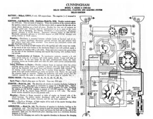
CUNNINGHAM MODEL V, SERIES 4 (1923-24) DELCO GENERATING, STARTING AND LIGHTING SYSTEM DELCO IGNITION BATTERY.—Willard, SJRN-5, 6 volt, 120 ampere-hour. The negative (—) terminal is grounded, IGNITION.—Coil Model No. 2135. ..Distributor Model No. 5218. Breaker contacts separ- ate 018 inch. They are made of tungsten. When the condition of the contacts affects the ignition, remove and resurface with fine emery cloth or against the flat side of an emery wheel, finishing on a hard oil stone. Breaker has two sets of contacts on an eight sided cam. Contacts must be synchronized so as to open at the same instant. This is important. See Timing. Distributor is semi-automatic. Maximum manual advance is 25-30 degrees. Automatic advance begins at 800 R.P.M. Maximum automatic advance is 12.5-14.5 degrees at 2100 R.P.M. Breaker arm spring tension is 16-20 ounces. Mounting :—Distributor is mounted between cylinder banks at forward end of en- gine. To remove distributor disconnect manual advance rod and primary lead and remove head with cables attached. Then remove two hold-down screws and lift distributor from place. ; oo fg View F / OILING.—Put 5 or 6 drops of light engine oil in the ignition unit oiler every two weeks. If the track of the rotor button in the distributor head is not well polished, apply a small amount of vaseline with a soft cloth. Once each year remove the grease plug on the side of the distributor housing and repack the housing with medium heavy cup grease. TIMING:—Synchronization of Contacts. To synchronize contacts, connect a 6 volt lamp across each set of contacts and crank engine slowly. Lamps will light as contacts open. If the two lamps do not light simultaneously loosen the three peo ing screits on breaker plate and shift the plate until correct synchronization is secured, Timing Distributor to Engine:—Breaker contacts begin to separate when the piston entering power stroke reaches a position 5 degrees after top dead center (meas- ured on the flywheel) with spark lever and breaker Phsk hi a fully retarded. To set timing, crank engine until piston No. | reaches firing position. Fully retard apark lever and loosen lockscrew in center of breaker cam. Rotate the cam until the contacts begin to separate. Tighten the lockscrew and make certain that the segment opposite the rotor is connected to the spark plug in cylinder No. 1. FIRING ORDER.—The firing order is IR, 4L, 3R, 2L, 4R, IL, 2R, 3L. Spark Plugs:—Spark plug gaps are 7% inch. Gaps are .030 inch. STARTER.—Model No. 183. The direction of rotation is counter-clockwise, looking at commutator end. The starter is connected to engine by a Bendix drive. Starter running free at 4000 R.P.M. takes a current of 60-70 amperes, 5.5 volts. Cranking the engine at 150 R.P.M. requires a current of 125-200 amperes, 5 volts, k torque is 24 lb. ft., current being 450-550 amperes at 2.75 volts, The starter brush tension should be 2!% to 234 pounds each. Mounting:—Starter is flange mounted at right of engine on forward side of fly- wheel housing. To remove starter, disconnect cable and remove three flange mounting screws. Pull starter forward, and lift out from underneath. OILING: — Put 8 or 10 drops of light engine oil in each of the starter bearing oilers every 1000 miles or each month. GENERATOR: — Model No. 182. The direction of rotation is clockwise, looking at the commutator end. The third brush system is used for current regulation. To adjust the charging rate, remove the cover hs and loosen the lock nut on the end of the generator. Then turn the third brush, plate adjusting screw in a clockwise direction amperes at 6 volts. to increase the charging rate and in the opposite direction to decrease the charging = st RS ©) STARTING pee ® | use Q° jevrrou! LE® | | cm (xy ?¢ © (G} = CUNNINGHAM MODEL V, SERIES 4 (1923-24) DELCO GENERATING, STARTING AND LIGHTING SYSTEM DELCO IGNITION rate, iY gem the lock nut after re tt the mal estnent The maximum charging rate is 18 amperes, reached at | . of the eee or 24 miles per hour. Generator motoring freely takes 3-5 amperes at 6 volts. Field current is Generator Test Data (Hot Test) Amperes R.P.M. M.P.H. 0 450. Gime 10 800. LT gy | [ne EIEN ARR IEN TOOO onc. eeeeccnan ZL OR 24 10-14 1450 ag 3 1800. The tension of each of the generator brushes should be a: ME lY4 to IY pounds, Mounting:—Generator is cradle mounted at front of engine. To remove generator, disconnect lead and remove bolts from hold-down clamp. Disengage coupling and lift generator from place. OILING.—Put 5 or 6 drops of light engine oil in the generator oilers every two weeks. If the car is driven more than 500 miles in two weeks, the oiling must be done every 500 miles. RELAY.—Relay closes at 10 miles per hour or 400 R.P.M. of the armature, and opens at 8 miles per hour or 320 R.P.M. of the armature. Relay contacts separate .046 to .062 inch. Air gap between relay armature (moving member) and coil core is .020 to .035 inch, contacts closed. To adjust relay, co