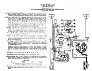
CUNNINGHAM SERIES V-7 (1927-28) SERIAL NOS. 5011 UP DELCO-REMY GENERATING, STARTING AND LIGHTING SYSTEM DELCO-REMY IGNITION BATTERY :—Willard, Type SJRR-5, 6 volt. Starting capacity is 145 amperes for 20 minutes. Lighting capacity is 5 amperes for 27 hours. The negative (—) terminal is grounded. Battery is mounted on right side of chassis under the front floor board. IGNITION :—Coil Model 2178. Distributor Model 5299. Breaker contacts separate .015-.020 inch. They are made of tungsten. Resurface contacts with a fine, flat contact file or on a medium hard oilstone. Breaker arm spring tension is 16-20 ounces. Distributor is semi-automatic. Maximum manual advance is 38° (engine). re advance begins at 800 R.P.M. and reaches a maximum of 15° at 2100 P.M. Breaker has two sets of contacts on an eight sided cam. They must be synchronized to open at the same instant. Connect a six volt lamp in each pri- mary circuit and shift breaker plate position until both lamps go out at the same instant. This will mean that contacts are correctly synchronized. Mounting :—Distributor is mounted at the forward end of the engine between the cylinder banks. To remove distributor, disconnect manual advance rod and breaker lead and remove distributor head or disconnect high tension cables. Then remove One hold down screw in manual advance arm and lift distributor from place. Oiling:—Put 8 or 10 drops of light engine oil in the oiler on the side of the distributor housing every month or each 1000 miles. Timing :—Breaker contacts begin to separate when piston No. | on compression stroke reaches top dead center with the manual spark control lever in the fully retarded position. At this point the flywheel marking “EX.C.IN.O.” will be opposite the in- dicator on the flywheel case. Valve Timing: INLET VALVES: :—Head diameter, 17% inches; stem diamter, .432 inch; stem length, 614 inch; tappet clearance, .0015 inch; spring pressure, 75 pounds; valve lift, 11/32 inch; intake opens at 5° past top dead center and closes 51° past lower dead center. EXHAUST VALVES:—Head diameter, 174 inches; stem diameter, .432 inch; stem length, 6% inches; tappet clearance, .003 inch; spring pressure, 75 pounds; valve lift, 11/32 inch; exhaust opens at 41° before bottom dead center and closes 5: past top dead center. Stem guides are removable. No oversize valve stems are made. Firing Order: —The firing order is 1R, IL, 4R, 4L, 2L, 3R, 3L, 2R. Spark Plugs:—Spark plugs are 7/8-18 S.A.E. Gaps are .031 inch. STARTER :—Model 350. Starter is connected to the engine through a Bendix drive. e direction of rotation is counter-clockwise, looking at the commutator end. Starter brush tension is 21/4-2!/4, pounds each. Starter Data Torque R.P.M. Volts Amperes 0 Ibs fee scesees AQOO sso Bi cee V9: sccesccccecccccestssasses | Bs scsesteserssesserrmin 500 Mounting:—Starter is flange mounted at right of engine. To remove starter, discon- nect starter cable and remove three flange mounting screws. Then slide starter from place. () / @ DISTRIBUTOR @) = © Ae E =| TONNEAU = SOF pest ae Fs a al «) = @ BREAKER @ a spor LiGHT O @ GS “ cs Fem ~~ = RESISTANCE UNIT St. CONDENSER r– IMD Del ‘ ie TR Te TA SIDE LIGHT UU 3 SIDE LICHT @ it) a4 » a 5 = = a” – & 3 5 ” > AMMETER ~ 3 5 2p 4 CUNNINGHAM SERIES V-7 (1927-28) SERIAL NOS. 5011 UP DELCO-REMY GENERATING, STARTING AND LIGHTING SYSTEM DELCO-REMY IGNITION Oiling:—Self-lubricating bearings are used. They require no attention. GENERATOR :—Model 285. The direction of rotation is clockwise, looking at the com- mutator end. Generator current regulation is by the third brush system. To adjust generator output, loosen locknut in generator end plate and shift third brush. Shift- ing the third brush in a clockwise direction increases the charging rate and in the opposite direction decreases the charging rate. Tighten the lock nut after making the adjustment. With maximum third brush Sie the output is $8-20 amperes at 7.5 volts reached at 1600 R.P.M. or 25 M.P.H Generator Data Amperes Volts Motoring generator draws 6 amperes at 6 volts. Shunt field current is 3 am- peres at 6 volts. Brush spring tension is 24-28 ounces. Mounting: —Generator is cradle mounted on front end of motor and is accessible from the left side of engine. To remove generator, disconnect generator lead and re- move lock nut and nut from hold down strap. Then lift generator from place. Oiling:—Put 8 or 10 drops of light engine oil in the generator bearing oilers every two weeks or each 500 miles. RELAY :—Model 5766. Relay is mounted on top of the generator. Relay contacts close when the voltage of the generator reaches 6.75-7.5 volts and open with a discharge current of 0-3 amperes. Relay contacts separate .015-.020 inch. Air gap between relay armature and coil core is .025-.035 inch, contacts closed. LIGHTING :—Delco-Remy Switch Model 1281. Switch is mounted on the instrument board. Dimming is by resistance on switch. Head, stop and backing cna are each 6-8 volt, 2] ep. S.C. M