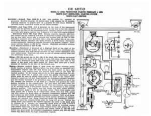
DE SOTO MODEL K (1929) PRODUCTION STARTED FEBRUARY 1, 1929 NORTH EAST GENERATING, STARTING SYSTEM NORTH EAST IGNITION BATTERY:—Willard, Type WSB-13, 6 volt. The positive (+) terminal is grounded. Starting capacity (20 minute rate) is 98 amperes for 20 minutes. Lighting capacity (5 ampere rate) is 5 amperes for 16.8 hours. Battery is (>) mounted under front floor boards on left frame member. “A 5 IGNITION :—Coil Type 21998. Coil is mounted on the back of the instrument board and the ignition switch, which is built in the base of the coil, extends through to the face of the instrument panel. Ignition current is 2.5 amperes at 6 volts with engine running and 5 amperes at 6 volts with engine stopped. Distributor Model TBU Type 10849. Breaker contacts separate .020 inch. Set contact gap by loosening lock nut on stationary contact stud and turn- ing up stud until correct gap is secured with breaker arm on lobe of cam. Resurface contacts when necessary with a fine flat contact file or on a me- dium hard oilstone. Breaker arm spring tension is 16-20 ounces. Distributor is semi-automatic. Maximum manual advance is 20 degrees (engine). Auto- matic advance begins at 600 R.P.M. (engine). Maximum automatic advance is 18 degrees reached at 2500 R.P.M. Mounting :—Distributor is mounted on a diagonal shaft at the right of the engine and is driven by a gear on the camshaft. To remove distributor dis- connect primary lead and manual advance rod and remove distributor head with cables intact. Then take out screw at rear of manual control lever and lift distributor from place. Oiling:—Fill the grease cup on the side of the shaft with medium cup grease and turn down two turns every month or each 1000 miles. At the same time remove the distributor head and rotor and saturate the wick oiler in the center of the shaft with light engine oil. Every 2000 miles put a small amount of vaseline on the face of the breaker cam. Timing:—Breaker contacts begin to open when the piston entering power stroke reaches a position .035 inch before top dead center on standard 5.2-1 compression engines and .008 inch before top dead center on 6.2-1 high compression head engines with the manual spark lever in the fully ad- vanced position. To set timing, remove the ¥% inch pipe plug from the cyl- inder head above No. 6 piston and screw the special micrometer gauge which must be used in timing these engines in place in the tapped hole. Connect a small six volt test lamp between the distributor primary terminal and the battery terminal of the generator relay. If the battery is out of the car, connect one terminal of the lamp to a battery and ground the other battery terminal to the engine block. The test lamp will burn when the breaker contacts are closed but will go out when the contacts open, serving as an accurate check of the contact opening. Set distributor in full manual advance position. Turn engine over and locate top dead center position. Set micrometer gauge at zero on top dead center. Then crank engine over until piston No. 1 comes up on compression stroke and stop with piston .035 inch before top dead center on standard compression engines and .008 inch before top dead center on high compression engines. Take up all back- lash in distributor gear by pressing rotor back against direction of rotation. Loosen the advance arm clamp screw and rotate the distributor counter- clockwise until the contacts break when the lamp will go out. Tighten the clamp screw and connect the segment opposite the rotor to the spark plug in cylinder No. 1. Connect the remaining spark plugs in order 5-3-6-2-4 Fv-1063. BREAKER 2) 2 DISTRIBUTOR ©) 3 ) RED 4 6) 6 6) BROWN BROWN FUSE BLOCK ICNITION COIL — Crim —-_ – oS vealihie Wg f, iF (5) si a IGNITION SWITCH Bioexj com com Lock F é © STOP LIGHT SWITCH STARTING SWITCH RED ® LJ GASOLINE GAUGE 5 Switce BLACK 3) e r > hn a XQ a LUE TAIL LIGHT clockwise around the distributor head. Check timing by cranking engine A wal —N NW, AK: UM over several times and then stop when ‘contacts break with piston No. 1 on (Vel = poo: Ucn, O te compression stroke. The gauge should read within limits of .030-.040 inch v before top dead center for standard compression engines and .006-.010 inch before top dead center for high compression engines. DE SOTO MODEL K (1929) PRODUCTION STARTED FEBRUARY 1, 1929 NORTH EAST GENERATING, STARTING SYSTEM NORTH EAST IGNITION Firing Order:—The firing order is 1-5-3-6-2-4, Spark Plugs:—Spark plugs are Champion Metric 18MM. Gaps are .027-.030 in – VALVE TIMING:—INLET VALVES:—Head diameter, 1 15/32 inches. Stem diam- eter, 11/32 inch. Stem length, 4 11/16 inches. Valve lift, 5/16 inch. Spring pressure, 88 pounds with valve open and 47 pounds with valve closed. Tap- pet clearance, .004 inch (hot). Inlet valves open 6 degrees after top dead center and close 46 degrees after lower dead center. EXHAUST VALVES:—Head diameter, 1 15/32 inches. Stem diameter, 11/32 inch. Stem length, 4 11/16 inches. Valve lift, 5/16