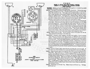
FORD MODEL T—SEDAN AND COUPE MODELS (1919-20) LIBERTY F. A. STARTING AND LIGHTING SYSTEM FORD IGNITION BATTERY :—Battery is 6 volt, 80 ampere-hour. The negative (—) terminal is g: ounded. IGNITION :—See ignition data on preceding page. Starter.—The starter is connected to the engine through a Bendix drive. Without load, starter should draw 70 amperes at 5.7 volts. It should crank the normal engine at 150 R. P. Mé, taking 160 amperes at 5 volts. Cold engine, heavy oil, tight bearings or other obstruc- tions, or damp, grounded or short circuited windings will cause high current and low speed during the cranking operation. Discharged, dry or sulphated battery, defective battery connections, defective switch contacts, defective starter connections, dirty commutator, high mica, dirty or sticking brushes, defective connections between armature coils and commu- tator bars or open circuits are the chief causes of low speed and low current. To remove the starter it is necessary to first remove the engine pan on the left hand side of the engine. Then remove the starter shaft cover from the transmission cover by taking out the four small screws. Turn the Bendix drive shaft around so that the set screw on the end of the shaft is in a horizontal position and points outward. Under the set screw is a lock washer with two extensions on opposite sides, one being turned against the collar and the other against the side of the set screw head. Bend back the extension which has been forced against the screw and remove the latter. Then pull the Bendix assem- bly out of the housing. Next remove the four screws which hold the starter housing to the transmission cover and pull out the starter, taking it down through the chassis. Oiling.—Starter requires no oiling. The rear bearing receives oil by splash from the Aly- wheel, and the forward bearing is of the oilless type. Generator.—Generator current regulation is by third brush method… Normal maximum output should be 10 amperes at 20 miles per hour, or 1200 R. P. M., of generator armature. Maximum output may be varied from 8 to 12 amperes by altering the position of the third brush. Third brush holder is fastened to the brush ring by a bolt which is free to move in a slot in the ring, when its nut is loosened. Cold resistance of the four field coils should be 2.45 chms. The generator is removed by taking out the three cap screws holding it to the front end cover, and forcing it backward and downward by insert- ing a screw driver between the generator and front end cover. If engine is run with bat- tery disconnected from the generator, be sure to ground the gcnerator terminal to the frame or engine. ( &% Oiling.—Put 4 or 5 drops of light engine oil in the rear bearing oiler every two weeks. If NS car is driven more than 500 miles in two weeks, the oiling must be done every 500 miles. RS Relay.—Relay is mounted either on the dash (see Plate 423), or on top of generator frame he) (Plate 424). Relay should close at 10 miles per hour or 600 R. P. M., of generator armature, and should open at 8 miles per hour, or 480 R. P. M., of generator armature. Charging current at closing should be 2-3 amperes, and discharge current 0-2 amperes = PORD at opening of relay contacts. Relay may be adjusted by bending the spring on the mov- x ET MODELS able arm or by adjusting the distance between the contacts. The contact points should g UBERTY STARTING $LIGHTING SYSTEM separate .032 inch, Clean relay contacts by drawing a piece of unglazed paper between, FORD IGNITION them. If badly bumed or pitted, resurface with a strip of worn No. 00 sand paper and then draw a piece of unglazed paper between them to remove all grit and adjust before again putting into service. i Lamps.—Head lamps are 6-8 volt, 17 cp. Dimmer lamps are 6-8 volt, 2 cp. Tail lamp Baal is 6°8 volt, 2 cp.