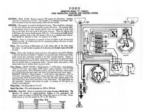
FORD IMPROVED MODEL “T” (1926-27) FORD GENERATING, STARTING AND LIGHTING SYSTEM FORD IGNITION BATTERY:—Ford. 6 volt. Starting capacity is 98 amperes for 20 minutes. Lighting capacity is 5 amperes for 17 hours. The negative (—) terminal is grounded. Bat- tery is mounted on the left frame member under the floor boards, IGNITION.—The magneto is carried in the flywheel housing. There should be a clearance of .031 inch, between the coil cores and the magnet pole pieces. The magneto deliv- ers alternating current to four vibrator ignition coils, one connected to each spark plug, as the timer closes the circuit in the proper sequence. When the vibrator arm is held down, the contacts should separate .030 inch, If the contacts are badly burned or pen resurface with a fine, flat jeweler’s file or on a medium hard oilstone. Coils should be adjusted to draw 1.3 amperes at 6 volts. Mounting:—Timer or commutator is mounted at front of engine on the forward end of the cam shaft. It is held in place by the commutator spring, a flat piece of metal bolted to the oil filler. Oiling.—Put several drops of light engine oil in the spring oiler of the timer every two weeks. In cold weather a mixture of 14 kerosene and 3% light engine oil should be used. Timing.—Timer roller should just make connection with segment connected to Number 1 coil when the piston in Number | cylinder is on top dead center of the power stroke, spark control lever and timer assembly in the fully retarded position. Number 1 coil is nearest the front of the engine and number | segment is the upper left hand terminal viewing timer from the front. Intake closes when piston is 3% inches below face of cylinder block on compression stroke. Exhaust opens when piston is 3% inches below face of cylinder block on power stroke. Valve Timing: —INLET VALVES:—Head diameter, | 15/32 inches; stem diameter, .3105 to .312 inch; stem length, 4.974 inches; tappet clearance, 1/32 to 1/64 inch; spring pressure, 30 to 34 pounds (open); valve lift, .225 inch; intake opens at 1/16 inch after top dead center and closes 9/16 inch past lower dead center. EXHAUST VALVES:—Head diameter, | 15/32 inches; stem diameter, .3105 to 312 inch; stem length, 4.974 inches; tappet clearance, 1/32 inch to 1/64 inch; spring pressure, 30 to 34 pounds (open); valve lift, .225 inch; exhaust opens 5/16 inch before lower dead center and closes at top dead center. The guide stems are not removable. Oversize valve stems are made. A variance of .312 inch is al- lowed in stem diameter. Firing Order.—The firing order is 1, 2, 4, 3. Spark Plug Gaps.—The spark plug gaps are .030 to .032 inch. STARTER.—Type F.A. Starter is connected to the engine through a Bendix drive. The direction of rotation is counter-clockwise, looking at the commutator end Starter cranks the engine at 500 R.P.M., taking 200 amperes at 3.4 volts. Starte: brush tension is 114-134 pounds for 50° to 70° deflection. Starter Data.—F.A. Torque .P.M Volts ins 5% 1 Ib. f.____EE——500_ 25 5 Ib. ft. 1050___ CY re 9 Ib. ft. 425, a 13 Ib. ft____ Lo O_____580 @) fl HORN BUTTON | | all 3 x ct Jo 1 ee 7 ee STARTING SWITCH 2S eenN TENNER TE HORN rr 8 a / 7 FORD IMPROVED MODEL “T” (1926-27) FORD GENERATING, STARTING AND LIGHTING SYSTEM FORD IGNITION Mounting :—Starter is mounted at left of engine on forward side of transmission case. To remove starter, remove four small screws holding Bendix drive cover at reat of transmission case. Remove cover and withdraw Bendix drive assembly after backing out set screw in end of starter shaft. Then remove four flange mounting screws holding starter on forward side of transmission case and slide starter for- ward. Starter can then be lifted from place. Oiling.—Starter requires no oiling. GENERATOR.—Type F A. Generator current regulation is by the third brush system. Direction of rotation is counter-clockwise, looking at the commutator end. Charging rate is varied by adjustment of the third brush setting. Loosen the clamp nut holding the third brush holder. Move third brush in the direction of armature rotation to increase the charging rate, or in the opposite direction to decrease the charging rate. Clamp the third brush after position adjustment. The generator fields draw 2.4 amperes at 6 volts. Generator Data.—F.A. Amperes Volts R.P.M. On ee | 68 ees Ef eT gop 9.0, 74 1100 11.5 7.9 1400 12.5 8.2 1700 11.0. 8.1 aD BA Generator motoring freely takes a current of 3 amperes at 6 volts. The generator brush tension is 2!/2 to 3 pounds for 50° to 70° deflection. Mounting:—Generator is flange mounted at right of engine at the rear of the gear case. To remove generator, back out four flange mounting screws. Then pry generator to rear and lift from place. Oiling.—Put 4 or 5 drops of light engine oil in the rear generator bearing oiler every two weeks. If the car is driven more than 500 miles in 2 weeks, the oiling must be done every 500 miles. RELAY.—Relay is mounted on the generator frame. Relay closes at 600-650 R.P.M. of