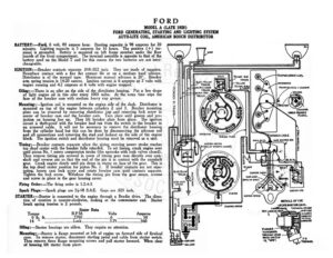
FORD MODEL A (LATE 1928) FORD GENERATING, STARTING AND LIGHTING SYSTEM AUTO-LITE COIL, AMERICAN BOSCH DISTRIBUTOR BATTERY :—Ford, 6 volt, 80 ampere hour. Starting capacity is 98 amperes for 20 minutes. Lig ting capacity is 5 amperes for 16 hours, The positive (+) ter- minal is grounded. Battery is mounted on left frame member under the floor boards of the front compartment. The terminal assemble is opposite to that of the battery used on the Model T and for this reason the two batteries are not inter- changeable. IGNITION:—Breaker contacts separate .018-.022 inch. They are made of tungsten. Resurface contacs with a fine flat contact file or on a medium hard oilstone. Distributor is of the manual type. Maximum manual advance is 20°. Breaker arm spring tension is 14-20 ounces, Ignition current is 6 amperes at 7 volts with engine running and 4.2 amperes at 6 volts with engine stopped. Oiling:—There is an oiler on the side of the distributor housing. Put a few drops of light engine oil in this oiler every 1000 miles. At the same time wipe the face of the breaker cam with medium heavy cup grease. Mounting:—Ignition coil is mounted on the engine side of the dash, Distributor is mounted on top of the engine between cylinders 2 and 3. Breaker mounting plate can be removed by removing distributor cap and removing lock screw in center of breaker cam and the breaker cam. Turn plate until groove and pro- jection on housing line up. Then lift breaker plate from place. The ignition circuit is theft-proof with the breaker lead run from the switch to the breaker in an armored ahs: It will not be necessary to remove the distributor housin from the cylinder head but this can be done by disconnecting the advance r and all connections and removing the stud and locknut on the side of the engine lock. The ignition switch and Suenbuntct housing must be removed as a unit. IRING IN HARNESS. WIRING TUBE LICHTING SWITCH Timing: —Breaker contacts separate when the piston entering power stroke reaches Nicurn or aor top dead center with the breaker fully retarded. To set timing, crank engine over until piston No. | enters compression stroke (the upstroke with both valves closed). en remove timing pin screwed in cover of timing gear case directly over cam- shaft and reverse pin so that the end of the pin is in contact with the camshaft _. Crank engine slowly until pin ores in recess on face of the gear. This is top dead center position for piston No. |. If breaker contacts are not sepa- rating, loosen cam lock screw and rotate breaker cam until contacts separate. Tighten the lock screw. Withdraw the timing pin from the gear recess, reverse and screw in place in the gear housing cover. Firing Order:—The firing order is |-2-4-3. Spark Plugs:—Spark plugs are 74-18 S.A.E. Gaps are .025 inch. STARTER:—Starter is connected to the engine through a Bendix drive. The direc- tion of rotation is counter-clockwise, looking at the commutator end. Starter brush spring tension is 2 pounds. Stater Data .M. Hq ELECTR wins ELD WY DETAILS OF THE statin swrtca _S2FORD IGNITION LOCK. Torque .P Volts Amperes ne SE SSS es ye Sn. i As cree: Loochsssescrcgesssee ssn asoc cy» terre 560 4 Oiling:—Starter bearings are oilless. They require no attention. PLUNGER “RR Mounting:—Starter is flange mounted at left of engine on forward side of flywheel at acre case. To remove starter, disconnect starting pedal and cable from starter switch. Then remove three flange mounting screws and pull starter forward. When clear of housing lift starter from place. FORD MODEL A (LATE 1928) FORD GENERATING, STARTING AND LIGHTING SYSTEM AUTO-LITE COIL, AMERICAN BOSCH DISTRIBUTOR GENERATOR:—The direction of rotation is counter-clockwise, looking at the com- mutator end. Generator current regulation is by third brush shunt fiel © ad- just generator output, remove the commutator cover cap and loosen the small screw holding the third brush on the fiber mounting ring. Then shift the third partment it is necessary to remove drive pulley and end cap. Mounting:—Generator is mounted on left of engine at forward end of engine by special swinging bracket and is belt driven from the crankshaft by the fan belt. brush in a counter-clockwise direction to increase _the charging rate and in the opposite direction to decrease the charging rate. Tighten the screw after making the adjustment. Generator brush spring tension should be 12-16 ounces each. Generator Data Amperes Volts R.P.M. V2 cccccsseccscecticasnecessasatttad y | eaeereeen ey av Lone 1500 Generator motoring draws 2.5-3 amperes at 6 volts. Shunt field current is 2 amperes at 6 volts. Generator stalled draws 22 amperes at 6 volts. Oiling:—Generator is equipped with ball bearings packed with cup grease. The grease compartment forms a hollow hub inside the armature and holds sufficient grease so that replenishing is necessary only infrequently. To repack grease com- © remove generator, disconnect lead and loosen bolts on adjustment bracket and mo