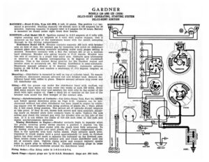
GARDNER MODELS 120 AND 125 (1929) DELCO-REMY GENERATING, STARTING SYSTEM DELCO-REMY IGNITION BATYERY:—Prest-O-Lite, Type 615-JFK, 6 volt, 15 plates. The positive (+): ter- —<—<—<—<—<$==== ° eee minal is grounded. Starting capacity (20 minute rate) is 120 amperes for 20 minutes. Lighting capacity (5 ampere rate) is 5 ampers for 20 hours. Battery is mounted on frame under right front floor boards. IGNITION :—Coil Model 528-Y. Ignition current is .6-2.5 amperes at 6 volts with engine running and 4.5 amperes at 6 volts with engine stopped. Coil is mounted on the back of the instrument board with the switch extending through to the driving compartment. Distributor Model 658-B. Breaker contacts separate .022 inch with breaker arm on lobe of cam. Set contact gap by loosening lock screw on stationary contact plate and turning eccentric adjusting screw until proper setting is Fs secured. Resurface contacts with a fine flat contact file or on a medium HORN BUTTON hard oilstaone. Breaker arm spring tension is 17-21 ounces. Breaker uses © two sets of contacts in a single four sided cam. Contacts open alternately at intervals of 45 degrees corresponding to 90 degrees of crankshaft rotation. This is the correct firing interval for the Gardner engine and = switcr breaker must be accurately set. See Timing. Distributor is semi-automatic. = = 29 9 f7"2-7" Maximum manual advance is 15 degrees (engine). Automatic advance begins at 500 R.P.M. and reaches a maximum of 17.5 degrees (engine) at 2000 R.P.M. Mounting :—Distributor is mounted in well on top of cylinder head. To remove distributor, disconnect manual advance rod and breaker lead. Remove dis- tributor head with cables in place. Remove manual advance stop screw and i Hi H Hf lift distributor out. x4 Oiling:—Fill the grease cup under the distributor head with medium cup grease and turn down one turn every two weeks or each 500 miles. Every =v 5000 miles remove the rotor and saturate the wick oiler in the center of the shaft with light engine oil. Plaee a small bit of vaseline on the face of the breaker cam under the fiber bumper of the contact arm. 4 TT 5 WN SS ho ses a ~ = -_——— i DISTRIBUTOR “sla * ya tj ~~, FUSE BLOCK OFOSOMORMOSOMONG BREAKER Timing :—Synchronization of Contacts:—Use Delco-Remy Tool, Part No. 820738, and follow special directions given on Page S-25. Contacts can be syn- chronized without tool after distributor has been timed to engine by crank- ing engine over 90 degdees from firing position of piston No. 1 when piston No. 6 will reach firing position. The second set of contacts should separate at this point. If they do not, loosen lock screws and turn eccentric adjust- ing screw on breaker plate until contacts begin to open. Tighten the lock screws and check the contact gap with the breaker arm on the lobe of the cam. If it is not within the limits of 018-.024 inch reset at .022 inch and repeat synchronization operation. Timing Distributor to Engine:—Breaker contacts begin to separate when the piston entering power stroke reaches a position 6 degrees (on the flywheel) before top dead center with the spark lever fully advanced. To set timing, crank engine over until piston No. 1 enters compression stroke. This is the upstroke with both valves closed. Fully advance spark lever. Continue to crank engine until a point approximately 1.6 teeth on flywheel before top dead center mark is opposite the indicator on the flywheel case. Then loosen clamp screw on advance arm and rotate distributor until one set of contacts open. Tighten clamp screw and connect segment oposite rotor to spark plug in cylinder No. 1. Connect remaining plugs in order 6-2-5-8-3-7-4 counter-clockwise around the distributor head. Firing Order:—The firing order is 1-6-2-5-8-3-7-4. Spark Plugs:—Spark plugs are %-18 S.A.E. Standard. Gaps are .030 inch. GARDNER MODELS 120 AND 125 (1929) DELCO-REMY GENERATING, STARTING SYSTEM DELCO-REMY IGNITION VALVE TIMING:—INLET VALVES:—Head diameter, 1 17/32 inches; stem diameter, 11/32 inch; stem length, 5%4 inches. Tappet clearance is .006 inch (hot). Spring pressure is 50 pounds (valve closed). Valve lift is 11/32 inch. Inlet valves open at top dead center and close 45 degrees after lower dead center. EXHAUST VALVES:—Head diameter, 1 17/32 inches; stem diameter, 11/32 inch; stem length, 5%4 inches. Tappet clearance is .008 inch (hot). Spring pressure is 50 pounds (valve closed). Valve lift is 11/32 inch. Exhaust valves open 50 degrees before lower dead center and close 10 degrees after top dead center. Valve stem guides are removable. Oversize valve stems are made. STARTER:—Model 716-A. Starter is connected to the engine through a Bendix drive. The direction of rotation is counter-clockwise, looking at the commutator end. Starter brush tension should be 24-28 ounces. Starter switch is Model 406-D. Starter Data Torque R.P.M. Volts Amperes OSIDE © Lb cekecciereoorntesseeceet SOOO... .ccrversccvssenfocopess a A A 70 Bh aie sassscscestoatseses SOCK i