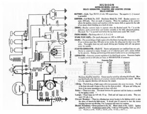
HUDSON SUPER-SIX MODEL (1917-18) DELCO GENERATING, STARTING AND LIGHTING SYSTEM @ I DELCO IGNITION © 3f BATTERY.—Exide, Type 3X-15-1, 6 volt, 100 ampere-hour. The negative (—) terminal 5 @ =3 is grounded, ze 5 & I IGNITION.—Coil Model No. 2127. Distributor Model No. 5147. Breaker contacts sep- “s z vt arate .018 inch. They are made of tungsten. When the condition of the contacts 8 Sie eS affects the ignition, remove and resurface with fine emery cloth or against the flat side = @ i) of an emery wheel, finishing on a hard oil stone TIMING.—Breaker contacts begin to separate when the flywheel mark “A—” is at the indicator, spark control Jever and breaker assembly in the fully advanced position. The mark “A—” is one-half inch before the top dead center mark “DC | & 6”. FIRING ORDER.—The firing order is 1, 5, 3, 6, 2, 4. SPARK PLUG GAPS.—The spark plug gaps are .025 to .028 inch. OILING.—Put several drops of light engine oil in distributor bearing oiler every two weeks. If car is driven more than 500 miles in two weeks, the oiling must be done every 500 miles. Thoroughly clean out and repack driving gear housing with soft cup grease every six months. STARTER-GENERATOR.—Model 82. Starter and generator are combined into one unit. Starter is connected to engine through a set of reduction gears and a pinion shifted by the operator. Raising and lowering of the motor brushes serves as a starting switch. DIMMER RESISTANCE HORN BUTTON | a 7] 8 5 iw z z ° ° ® 3 ba CONDENSE TIMING CONTACTS aN = 9 RESISTANCE UNIT CQO z F é. 5 Ra i} GENERATOR.—Generator current regulation is by third brush system. Generator begins I Zo ee a to supply current at 6-8 miles per hour, or 450-500 R.P.M. of armature. 4 CA UL ao 3 ‘ 3 Generator Data a | a) x (s) THIRD BRUSH 1CN CJ GENERATOR SHUNT FIELD Machines should be tested hot. Output may be varied by adjusting third brush. Mov- ing third brush in the direction of armature rotation will increase the output. Moving it in the opposite direction will decrease the output. Oiling.— Put 6-8 drops of light engine oil in rear generator oiler every two weeks. Put oil in the front oiler until it begins to flow out the drain provided. All gears and «liding sur- faces of the starter transmission must be kept well oiled. SHUNT FIELD TERMINAL SWITCH GENERATOR TERMINAL OPERATED BY STARTING PEDAL each 3-4 volt, 2 cp. Circuit Breaker.—There is a vibrating type circuit breaker in the lighting switch to take the place of fuses in the light circuits. It should take 25 amperes to start this device vibrating, but once set vibrating, 3 to 5 amperes will cause it to continue. Model Numbers.—Motor-generator is No. 82. Motor clutch is No. 12207. Ignition coil is No. 2127. Combination switch is No. 1106 on 1918 and No. 1071 on 1917 anve DYetthutante Nia S1AT an 1012 and Na &1%A an 1017 anen ~ $2 Relay.—There is no relay. The circuit between the generator and the battery ts controlled «o” «s