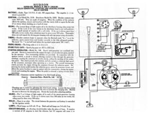
HUDSON SUPER-SIX, MODELS N AND O (1919-20) DELCO GENERATING ,STARTING AND LIGHTING SYSTEM DELCO IGNITION BATTERY.—Exide, Type 3-X-15-1, 6 volt, 100 ampere-hour. The negative (—) ter minal is grounded. IGNITION.—–Coil Model No. 2170. Distributor Model No. 5203. Breaker contacts sep- arate .018 inch. They are made of tungsten. When the condition of the contacts affects the ignition, remove and resurface with fine emery cloth or again the flat side of an emery wheel, finishing on a hard oil stone OILING.—Put several drops of light engine oil in the distributor bearing oilers every twa weeks. If the track of the rotor button in the distributor head is not well polished, apply a small amount of vaseline with a soft cloth. If the car is driven more than 500 miles in two weeks, these attentions must be given every 500 miles. Thoroughly clean out and repack the driving gear housing with soft cup grease every six months. TIMING.—Breaker contacts begin to separate when the flywheel mark “A—” is at the indicator, spark control lever and breaker assembly in the fully advanced position. The mark “A—” is one-half inch before the top dead center mark “DC | & 6”. FIRING ORDER.—The firing order is 1, 5, 3, 6, 2, 4. SPARK PLUG GAPS.—Spark plug gaps are .025 to .028 inch. STARTER-GENERATOR.—Model No. 140. Starter and generator are combined into one unit. Starter is connected to the engine through a set of reduction gears, meshed by the operator. Two overrunning clutches are provided. In connection with the ignition switch, a circuit is closed, allowing current to flow through the generator windings, causing the armature to revolve slowly, aiding the meshing of the reduc- tion gears. One clutch permits this rotation, and also permits a relatively high speed of the armature, necessary when operating as a starter. The second overrunning clutch prevents the engine driving the armature through the reduction gears. De- pressing the starter pedal meshes the reduction gears, opens the generator circuit, and allows the motor brushes to come in contact with the commutator, closing the starter circuit and cranking the engine. When the pedal is released, a spring reverses these operations. GENEKA1UK.—Generator current regulation is by third brush system. Amperes Generator Data—Model No. 140 R.P.M. 0 ee 440 A ET IT EO a hn ney 1300 1-422 ees oe 2000 8-11. — 2500 Charging rate is varied by adjusting the third brush setting. Loosen the two screws in the third brush arm, and lengthen the arm to increase the charging rate. Shorten the arm to decrease the charging rate. Reseat the brush after adjusting position. OILING.—Put 5 or 6 drops of light engine oil in each of the starter-generator bearing oilers every two weeks. If the car is driven more than 500 miles in two weeks, the oiling must be done every 500 miles, RELAY.—There is no relay. The circuit between the generator and battery is controlled by the ignition switch. LAMPS.—Head lamps are 6-8 volt, 15 cp. Dash and tail lamps are 3-4 volt, 2 ep. CIRCUIT-BREAKER.—A vibrating circuit-breaker takes the place of fuses. It requires a current of 25 amperes to start the vibrator. but 3-5 amperes will cause it to 0) ‘