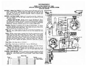
HUPMOBILE MODEL A-6 ‘NEW CENTURY SIX’ (1928) AUTO-LITE GENERATING, STARTING AND LIGHTING SYSTEM AUTO-LITE IGNITION BATTERY :—Willard, Type CRR-15, 6 volt. Starting capacity (20 ampere rate) is 114 amperes for 20 minutes. Lighting capacity (5 ampere rate) is 5 amperes for 20 hours. Battery has 15 plates each 434 inches high, As inches wide and 3/32 inch thick. The positive (+) terminal is grounded. Battery is mounted under the front seat on the left side. IGNITION: —Coil Model IG-4065. Ignition coil is mounted on the dash. Ignition cur- rent is 1-3 amperes at 6 volts with engine running and 3.4-5 amperes at 6 volts with engine stopped. Distributor Model IGC-4001. Breaker contacts separate .020-.024 inch. Resur- face contacts with a fine flat contact file or on a medium hard oilstone. Breaker arm spring tension should be 16 ounces. Distributor is semi-automatic. Maximum manual advance is 15° (distributor). Automatic advance begins at 500 R.P.M. (distributor). Maximum automatic advance is 8° reached at 1800 R.P.M. Mounting: —Distributor is mounted at left of engine by special flange. To remove distributor, disconnect manual advance rod i a primary lead and remove distrib- utor head with high tension cables intact. Then remove set screw on side of dis- tributor mounting and lift distributor from place. Oiling:—Put 4 or 5 drops of light oil in the oiler on the side of the distributor ever 500 miles. Put a small amount of vaseline on the face of the breaker cam every 1000 miles. Timing:—Breaker contacts begin to separate when the piston entering power stroke reaches top dead center with manual spark lever fully retarded. To set timing, crank engine until piston No. | enters compression stroke. This is the upstroke with both valves closed. Fully retard spark lever and continue to crank engine until piston reaches top dead center. Loosen advance arm clamp screw and rotate distributor until contacts begin to separate. Tighten the clamp screw. Make cer- zm pat the rotor is opposite the segment connected to spark plug in cylinder o. I, Firing Order:—The firing order is 1-5-3-6-2-4. Spark Plugs:—Spark plugs are 74-18 S.A.E. Gaps are .022-.025 inch. VALVE TIMING:—Specifications: Head diameter, 11/4 inches. Valve lift, 5/16 inch. Tappet clearance, .005 inch oe and .006 inch (exhaust). Timing:—Inlet valves open 4 degrees after top dead center and close 51 de- grees after lower dead center. Exhaust valves open 47 degrees before lower dead center and close at top dead center. STARTER:—Model MN-4109. Starter is connected to the engine through an inboard en rive. e direction of rotation is counter-clockwise, looking at the com- eee Brush spring tension is 114-114. pounds. Starter switch is Model Starter Data Torque R.P.M. Volts Amperes Oolb? fhessscccscxseco Pree: seco ecu: Shs Se eT erate 45 (No Bendix) 0 te ee. Freese ees 55: mscomseveenerene 50 (With Bendix) Be eee ee cccrssceecaeas 2800… .eecsecereneeceene Lk ee nen: 100 ZAD OS oc [E. 2) | re CX | ROE noes 200 iG cree! Seto O50 essere 45 cccnecenecencereeee …300 7&7 5a | 7 Se ne V3.0) 25) cect Lock sccstesstccasscs BOs oso 620 fl BLACK GREEN STOP LIGHT @BACKING LIGHT G TAIL LIGHT G « – i ’ | 2 2 o ARMORED CABLE BP i a | RELAY | s— =8. $f = | Yoon Se as 7 ——~ GENERATOR DOME LICHT ans SWITCH TANG DASH LIGHT 5 7 F} ‘om AMMETER HUPMOBILE MODEL A-6 ‘NEW CENTURY SIX’ (1928) AUTO-LITE GENERATING, STARTING AND LIGHTING SYSTEM AUTO-LITE IGNITION Mounting:—Starter is mounted at left of engine on forward side of flywheel housin by standard S.A.E. No. | flange mounting. To remove starter, disconnect cable an remove three flange mounting cap screws. en pull starter forward and lift from place. Oiling:—Put 4 or 5 oon of light oil in the oiler on the commutator end of the starter every 1000 miles. GENERATOR:—Model GAJ-4101. The direction of rotation is counter-clockwise, look- ing at the commutator end, Generator current regulation is by third brush shunt field. To adjust generator output, remove cover band and shift third brush by pressure on mounting bracket. Shift the third brush in a counter-clockwise direc- tion to increase the charging rate and in the opposite direction to decrease the charging rate. The third brush is held in position by friction between the mount- ing bracket and the end plate. Maximum charging rate is 15 amperes (cold) reached at 1600 R.P.M. Generator Data Cold Test Hot Test Amperes Volts R.P.M. = Amperes Volts R.P.M. 12.8 7.6 ….1200 15 0 ….1600 UNF 2 ad B.0..[…..-f. 0. 1900 13.4 78 ….2000 11.7 7.5 2400 Brush Dees sisi oe is 214-234 pounds each. A five ampere field fuse is mounted on the generator. Mounting :—Generator is mounted at right of engine on rear of timing chain case by standard S.A.E. flange mounting. To remove generator, disconnect generator wire and back off timing chain adjusting set screw. Then remove three flange mount- ing cap screws and pull generator to rear being careful not to disturb the timing ain. Timing Chain Adjustment:—The