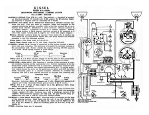
KISSEL MODEL 6-70 (1928) DELCO-REMY GENERATING, STARTING SYSTEM DELCO-REMY IGNITION BATTERY :—Willard, Type WR-13, 6 volt. The positive (+) terminal is ground- ed. Starting capacity (20 minute rate) is 98 amperes for 20 minutes. Light- ing capacity (5 ampere rate) is 5 amperes for 17 hours. IGNITION :—Coil Model 525-C. Distributor Model 636-S. Breaker contacts sep- arate .025 inch. They are made of tungsten. When the condition of the contacts affects the ignition resurface with a fine flat contact file or on a medium hard oilstone. Distributor is semi-automatic. Manual advance is 22 degrees (engine). Automatic advance is 21 degrees (engine). Breaker arm spring tension is 18-20 ounces. Ignition current is 3.5 amperes at 6 volts with engine running and 6 amperes at 6 volts with engine stopped. Timing:—Breaker contacts begin to separate when piston No. 1 reaches top dead center on the compression stroke, with the spark control and breaker assembly in the fully retarded position. Firing Order:—The firing order is 1-5-3-6-2-4. Spark Plugs:—Spark plugs are 7% inch Long. Gaps are .025 inch. STARTER:—Model 716-A. Starter is connected to the engine through a Bendix drive with gear reduction. The direction of rotation is clockwise, looking at the commutator end. Starter cranks the engine drawing 175-180 amperes at 4.5 volts. Brush spring tension is 24-28 ounces. Starter Data Torque R.P.M Volts Amperes OSD. fi accent $000 3. 2c § deeb ne Ee 70 1S: Ib: fhe Lock: :cebehes Le by 1 fies fre Rang ne RCO 450 Oiling:—Put 4 or 5 drops of light engine oil in the oiler on the commutator end of the starter every 1000 miles. The drive end bearing is oilless. GENERATOR:—Model 949-C. The direction of rotation of the generator is coun- ter-clockwise, looking at the commutator end. Current regulation is by the third brush system combined with a thermostat. Thermostat contacts open at 150 degrees F. reducing the output approximately 40%. To adjust gener- ator output, loosen the screw on the generator end plate and shift the third brush mounting plate in a counter-clockwise direction to increase the charging rate and in the opposite direction to decrease the charging rate. Generator Data Cold Test Hot Test Amperes Volts R.P.M. Amperes Volts R.PM. oy | ee a 1450 Q—1Z,…caccscdygeore (oe 2000 Generator, motoring, draws 5.5 amperes at 6 volts. Shunt field current is 5 amperes at 6 volts. Generator brush spring tension is 24-28 ounces. Oiling:—Put 4 or 5 drops of light engine oil in the generator oilers every month or each 1000 miles. RELAY :—Model 265-B. Relay is mounted on the generator. Relay contacts close at 675 R.P.M. of the generator armature or 6-7 M.P.H. when the generator voltage reaches 6.75 volts. Contacts open with a discharge current of 2.5 amperes. Relay contacts separate .015-.025 inch. Air gap between relay ar- mature and coil core is .014-.021 inch with contacts closed. LIGHTING :—Olum Switch Model 10677. Lighting switch is mounted at the base of the steering column. Head lights are 6-8 volt, 21 cp. S.C. Mazda 1129. Side lights are 6-8 volt, 3 cp. S.C. Mazda 63. Dash and tail lights are 6-8 vor 3 cp. S.C. Mazda 63. Stop and backing lights are 6-8 volt, 15 cp. S.C. azda 87. FUSES :—Lighting fuses are 10 amperes. @ DIMMER RESISTANCE HORN BUTTON JUNCTION BLOCK IGNITION SWITCH STARTING SWITCH PonerOn So@| { oo Fy A ( Ge STOP LIGHT.