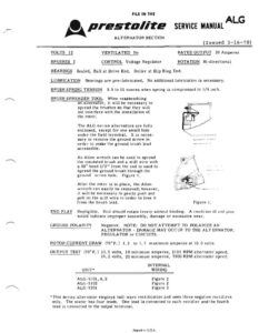
FILE IN THE @, prestasite SERVICE MANUAL | Nad ALTERNATOR SECTION ALG (Issued 3-16-78) VOLTS 12 VENTILATED No RATED OUTPUT 20 Amperes BRUSHES 2 CONTROL Voltage Regulator ROTATION Bi-directional BEARINGS Sealed, Ball at Drive End, Roller at Slip Ring End. LUBRICATION Bearings are pre-lubricated. No additional lubrication is necessary. BRUSH SPRING TENSION 9,5 to 11 ounces when spring is compressed to 1/4 inch, BRUSH SPREADER TOOL When reassembling an alternator, It wlll be necessary to Spread the brushes so that they will not interfere with the installation of the rotor, The ALG Series alternators are fully enclosed, except for one small hole under the field terminal, It is neces- NN, Ant ys wines ee sary to remove the ground screw in Pe ae order to make the ground brush lead eek] verre ot accessible. An Allen wrench can be used to Spread A) 4 the insulated brush and a stiff wire with @, a 90° bend 1/2″” from the end is used to spread the ground brush through the ground screw hole, Figure 1. After the rotor is in place, the Allen wrench can easily be removed; however, it will be necessary to gently push and pull on the stiff wire in order to free it from the brush lead. Figure lL. END PLAY Negligible, Unit should rotate freely without binding. A condition of end play would indicate improper assembly, damage or excessive wear, GROUND POLARITY Negalive. NOTE: DO NOT ATTEMPT TO POLARIZE AN ALTERNATOR – DAMAGE MAY OCCUR TO THE ALTERNATOR, REGULATOR or CIRCUITS. ROTOR CURRENT DRAW (70°F.) 1.3 to 1.7 maximum amperes at 10.0 volts. OUTPUT TEST (70°F,) 13.5 volts, 10 minimum amperes, 2100 RPM alternalor speed, 14.2 volts, 20 minimum amperes, 5900 RPM alternator speed. INTERNAL UNIT* WIRING ALG-5101, 4,8 Figure 2 ALG-5102 Figure 2 ALG-5201 Figure 3 *This series alternator employs half-wave rectification and uses three negative rectifiers only, The stator has four leads, One lead is connected to each rectifier and the fourth lead is connected to the output terminal. Printed In U.S.A. (ALG Continued) rN Prestasite SERVICE MANUAL Figure 2 Figure 3 Primed (In U.S.A.