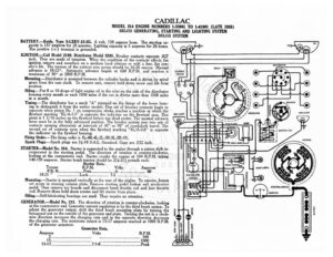
CADILLAC MODEL 314 ENGINE NUMBERS 1-33001 TO 1-41001 (LATE 1926) DELCO GENERATING, STARTING AND LIGHTING SYSTEM DELCO SYSTEM BATTERY.—Exide, Type 3-LXRV-15-2G. 6 volt, 130 ampere hour. The starting ca- pacity is 137 amperes for 20 minutes. Lighting capacity is 5 amperes for 26 hours. The positive (+) terminal is grounded. IGNITION.—Coil Model 2189. Distributor Model 5281. Breaker contacts separate .027 inch, They are made of tungsten. When the condition of the contacts affects the ignition remove and resurface on a medium hard oilstone or with a fine, flat jew- eler’s file. The tension of the contact arm spring should be 16-20 ounces. Manual RELAY (eee advance is 18-22°. Automatic advance begins at 600 R.P.M. and reaches a ucHT™ Tae maximum of 30° at 2800 R.P.M. Mounting.—Distributor is mounted between the cylinder banks and is driven by spiral bee gears from the cam shaft. To remove unit, remove hold down screw and lift from a“ position. Oiling.—Put 8 or 10 drops of light engine oil in the oiler on the side of the distributor housing every month or each 1000 miles if the car is driven more than 1000 miles in a month. Timing.—The distributor has a mark “A” stamped on the flange of the lower hous- ing to distinguish it from the earlier models. One set of breaker contacts begin to separate when piston No. | on compression stroke reaches a position at which the ceninaaen flywheel marking “IG/A-1-5” is opposite the indicator on the flywheel case. This 5 Ps oint is | ae inches on the flywheel before top dead center. The manual advance @/ lovee must be in the fully advanced position. The breaker system uses two sets of u contacts opening alternately at intervals of 45° or 90° of crankshaft travel. The second set of contacts open when the flywheel marking “IG/A-2-6” is opposite e indicator on the flywheel housing. Firing Order.—The firing order is 1L-4R-4L-2L-3R-3L-2R-IR. Spark Plugs.—Spark plugs are 74-18 S.A.E. Standard. Gaps are .032 inch. STARTER—Model No. 314. Starter is connected to the engine through a pinion shift in- corporated in the starting pedal. e direction of rotation is counter-clockwise, looking at the commutator end. Starter cranks the engine at 104 R.P.M. taking ae Wer Horn vo! i G i INSPECTION LIG! 140-150 amperes. Starter brush tension should be 214-2) pounds each. HESS tT sate Data. Vol Am CIGAR LIGHTER — orque VL. olts peres O Ib. ft. eee Pree? iccsescnccco NN 6. £….4..2.> . 60 RW, T8258″ noes Lock: chee b> ener se ER a Ba Mounting.—Starter is mounted vertically at the rear of the engine. To remove, loosen set screw in steering column plate. Resove starting pedal button and accelerator pedal. Then remove toe Boatds and disconnect hand throttle rod and foot throttle rod. Remove three hold down screws and lift starter from place. Oiling.—Self-lubricating bearings are used. They require no attention. GENERATOR.—Model No. 315. The direction of rotation is counter-clockwise, looking at the commutator end. Generator current regulation is by the third brush system. To adjust the generator output, shift the third brush mounting plate by turning the hexagonal nut on the outside of the generator end plate. Turning the nut in a clock- § wise direction increases the charging rate and in the opposite direction decreases the charging rate. The maximum output is 15-17 amperes reached at 1000 R.P.M. i of the generator armature. IGNITION SWITCH ba c : STARTING SWITCH! ad A, AMMETER F & E a Generator Data. 3 Amperes Volts R.P.M. CADILLAC MODEL 314 ENGINE NUMBERS 1-33001 TO 1-41001 (LATE 1926) DELCO GENERATING, STARTING AND LIGHTING SYSTEM DELCO SYSTEM The brush tension should be 1-114 pounds each. Shunt field current is 3 amperes at 7.5 volts. Mounting.—Generator is mounted at the front of the engine between the cylinder banks and is belt driven. Care must be taken to see that the belt is not tight enough to crowd the generator bearings nor so loose that excessive slipping is possible. To remove generator, loosen the four mounting nuts at the forward end of the gen- erator and lower the unit so that the belt can be removed. Then remove nuts and lift generator from position. Oiling.—Put 8 or 10 drops of light engine oil in each of the generator bearing oilers every two weeks or each 500 miles if the car is driven more than miles in two weeks. RELAY.—Relay contacts close at 10-12 M.P.H. when the voltage of the generator reaches 6.75-7.5 volts and open with a discharge current of 0-3 amperes. Air gap between relay armature and coil core is .009-.010 inch, contacts closed. LIGHTING.—Switch Model 1303. Head lamps use a double filament bulb. They are 6-8 volt, 21 cp. Dimmer lamps are 6-8 volt, 3 cp. S. C. Dash, dome, tonneau_and tail lamps are 6-8 volt, 3 cp. S.C. Backing and stop lamps are 6-8 volt, 21 cp. S. C. CIRCUIT BREAKER.—Model 5767. A combined vibrating and lockout circuit breaker is mounted on the dash. The vibrating unit protects the lighting circuits. A cur- rent of 25-30 amperes causes it to operate. While vibrating the current flow is 10-15 amperes. The lockout circuit breaker protects the horn, inspection lamp, stop and backing lamp and cigar lighter circuits. A current of 25-30 amperes causes it to open the circuit. While operating the current dow is less than | ampere.