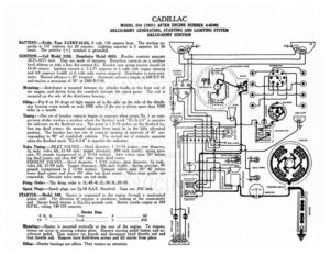
CADILLAC MODEL 314 (1927) AFTER ENGINE NUMBER 4-41001 DELCO-REMY GENERATING, STARTING AND LIGHTING SYSTEM DELCO-REMY IGNITION BATTERY:—Exide, Type 3-LXRV-15-2G, 6 volt, 130 ampere hour. The starting ca- city is 137 amperes for 20 minutes. Lighting capacity is 5 amperes for 26 [1 tl : fous, The positive (+) terminal is crounted @sS Qe IGNITION:—Coil Model 2195. Distributor Model 4016. Breaker contacts separate ihe -0225-.0275 inch. They are made of tungsten. Resurface contacts on a medium al hard oilstone or with a fine, flat contact file. Breaker arm spring tension should be ee COMP CHSATING FIELD 16-20 ounces. Ignition current is .5-2.75 amperes at 6 volts with engine running A De GN and 4.8 amperes (cold) at 6 volts with engine stopped. Distributor is semi-auto- | ment cn —_— ~~ matic. Manual advance is 20° (engine). Automatic advance begins at 600 R.P.M. and reaches a maximum of 30° at 2800 R.P.M. a Mounting: —Distributor is mounted between the cylinder banks at the front end of the engine, and driven from the camshaft through the spiral gears. The coil is mounted on the side of the distributor housing. Oiling:—Put 8 or 10 drops of light engine oil in the oiler on the side of the distrib- utor housing every month or each 1000 miles if the car is driven more than 10 miles in a month, ok @) >) @) a “3 » = g Rie > ee 5) ° —_ / == / te a9 7 Ss 270-7 worn ~ – HORN BUTTON a VA a 1314 LNNHS ¢ HSAYS QYIHL ~ sa ~. 4 t 1 er . F Com Y/ “i / : CONDENSER Timing:—One set of breaker contacts begins to separate when piston No. | on com- pression stroke reaches a position where the flywheel mark “IG/A-1-5” is opposite @)/ a @/ the indicator on the flywheel case. This point is 1 3/16 inches on the flywheel be- — “Us O fore top dead center; the manual advance lever must be in the fully advanced 7 TTT cl 7 2 > position. The breaker has two sets of contacts opening at intervals of 45° cor- ——— ATE) ics area mag responding to 90° of crankshaft rotation. The second set of contacts separate STNG, iow when the flywheel mark “IG/A-2-6” is opposite the indicator. yy . caprengoreen Valve Timing: —INLET VALVES:—Head diameter, | 11/16 inches; stem diameter, ¥% inch; valve lift, 21/64 inch; tappet clearance, .004 inch (cold); spring pres- sure, 95 pounds (compressed to 2 15/64 inches). Inlet valves open 18° before top dead center and close 64° 40’ after lower dead center. EXHAUST VALVES:—Head diameter, | 9/16 inches; stem diameter, 3 inch; valve lift, 21/64 inch. Tappet clearance, .006 inch (cold). Spring pressure, 95 unds (compressed to 2 15/64 inches). Exhaust valves open 56° 40° before ower dead center and close 10° after top dead center. Valve stem guides are removable. Oversize valve stems are not made. Firing Order:—The firing order is 1L-4R-4L-2L-3R-3L-2R-IR. Spark Plugs:—Spark plugs are 74-18 S.A.E. Standard. Gaps are .032 inch. STARTER:—Model 349. Starter is connected to the engine through a mechanical pinion shift. The direction of rotation is clockwise, looking at the commutator end. Starter brush tension is 2!/4-2!/ pounds each. Starter cranks engine at 104 R.P.M., taking 140-150 amperes. INSPECTION LIG! “HSS i). mc) i; | eg CIGAR LIGHTER Vy ‘ DASH LAMPS. q SN = 5 STARTING SWITCH! ed AMMETER CIRCUIT BREAKER oO > > SWITCH I I SWITCH C8 oie 0: BATTERY Starter Data 19°” aegerroeesrcnees Locksssesetes ee Be Seesaw 450 e Ss – Mounting:—Starter is mounted vertically at the rear of the engine. To remove, . § loosen set screw in steering column plate. Remove starting pedal button and ac- §& g celerator pedal. en remove toe boards and disconnect hand throttle rod and = 4 foot throttle rod. Remove three hold-down screws and lift starter from place. sabe a . ; . . MOOOw * Oiling.—Starter bearings are oilless. They require no attention. CADILLAC MODEL 314 (1927) AFTER ENGINE NUMBER 1-41001 DELCO-REMY GENERATING, STARTING AND LIGHTING SYSTEM DELCO-REMY IGNITION GENERATOR :—Model 370. The direction of rotation is counter-clockwise, looking at the commutator end. Generator current regulation is by the third brush system. Adjustment of the third brush is secured by removing the strap and moving the third brush by hand. Shifting the third brush in a counter-clockwise direction increases the charging rate and in the opposite direction decreases the charging rate. The third brush is held in any desired position by friction washers. Conccabat is of the split field type with the third brush shunt field wound on only one field pole. A straight shunt field in series with a thermostat is wound on the other field pole. Thermostat contacts open at 175°F., cutting a resistance in the field circuit and rendering the straight shunt field inoperative. Generator then runs as a third brush machine with reduced output. With maximum setting, generator output is 22 amperes at 8.6 volts reached at 1400-1600 R.P.M. Brush spring tension is 16-20 ounces. Third brush shunt field current is 4.5 amperes at 6.5 volts. Straight shunt field current is .75 amperes