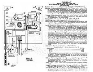
a LIGHTING AND ¥ JGNITION SNITCH AMMETER TROUBLE LAMP SOCKET te @)7ONNEAU LAMP CADILLAC MODEL S7(1919) DELCO SYSTEM STARTER-GENERATORP MOUNTED IN ALVE VALLEY CADILLAC Model 55 (1917-18) 57 (1918, 1919 DELCO GENERATING, STARTING AND LIGHTING SYSTEM DELCO IGNITION Battery.—Battery is 6 volt, 150 ampere-hour. The positive (-+) terminal is grounded. Ignition.—Breaker contacts should separate .018 inch. They are made of tungsten. They will operate even though very irregular, due to the fact that the rough surfaces fit each other perfectly. Their natural color is dark gray, not silver. Should they become badly burned or pitted, affecting the ignition, remove and resurface them by drawing across a piece of fine emery cloth laid on a flat surface, as on the bed of a drill press, finishing on a very hard oil stone. Clean all oil from contacts before again putting into service. Timing.—Breaker contacts should separate when flywheel marking “l-GA” is directly under indicator, No. | piston of left-hand block entering power stroke, spark control lever and breaker assembly in fully retarded position. Firing Order.—The firing order is IL, 2R, 3L, 1R, 4L, 3R, 2L, 4R. Spark Plug Gaps.—Spark plug gaps should be .028 inch to .030 inch. Oiling.—Every 2000 miles remove the breather pipe on the ignition unit and pack the gears with soft cup grease. If track of rotor button inside distributer head is not well polished, apply a very small amount of vaseline with a soft cloth. Starter-Generator.—Starter and generator are combined into one unit, but are electrically separate. Starter is connected to the flywheel through a pinion shifted by the operator. Two overrunning clutches are provided. In connection with the ignition switch, a circuit is closed allowing a current flow through the generator windings causing the armature to revolve slowly, facilitating the meshing of the reduction gears. One clutch permits this rotation, and also permits a relatively high speed of the armature, necessary when operat- ing asastarter. “The second overrunning clutch prevents the engine from driving the arm- ature through the reduction gears. Depressing the starting pedal meshes the reduction gears, opens the generator circuit, and allows the motor brushes to come in contact with the commutator, closing the starter circuit and cranking the engine. When the pedal is released, a spring reverses these operations, When running freely, starter turns at 4000- 4500 R. P. M., drawing 50-70 amperes. Cold engine, heavy oil, tight bearings or other obstructions, or damp, grounded or short circuited windings will cause high current and low speed during the cranking operation. Discharged, dry or sulphated battery, defective battery connections, defective switch contacts, defective starter connections, dirty commutator, high mica, dirty or sticking brushes, defective connections between armature coils and commutator bars or open circuits are the chief causes of low speed and low current. Generator.—Generator current regulation is by third brush system. GENERATOR Data. Motor-GeEnerator No. 98 Output-Amperes ; R. P. M. EU PTT pata, emt Sinn ERY arate seerrerice ar eee ee ee 500 nO- 12%… ee ee ed ee ee | When motoring with the overrunning clutch as the only retarding force, generator takes 4.5 amperes. To adjust the charging rate, loosen the two screws on the movable arm holding the third brush. If desirous of increasing the charging rate, the arm should be lengthened, and shortened to decrease it. Oiling.—Put 4 or 5 drops of light engine oil in starter-generator oiler every two weeks. At the same time inject Cadillac rear axle and transmission lubricant in elbow oiler at rear of starter shaft with grease gun. If car is driven more than 500 miles in two weeks, these attentions must be given every 500 miles. Relay.—There is no relay. Circuit between generator and battery is controlled by ignition switch. Lamps.—Head lamps are 6-8 volt, 20 cp. Side lamps are 6-8 volt, 6 cp. Tail and dash lamps are in series, and are each 3-4 volt, 2 cp. Tonneau lamp is 6-8 volt, 2 cp. Circuit Breakers.—There is a vibrating breaker in the circuit to the head, side, dash and tail lamps, which takes the place of fuses. It requires a current of 25 amperes to start this device vibrating, but when vibrating a current of 3 to 5 amperes will cause it to con-