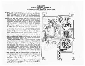
CADILLAC SERIES 341 (1927) SERIAL NOS. 3-06001 UP SERIES 341-A (1928) DELCO-REMY GENERATING, STARTING AND LIGHTING SYSTEM DELCO-REMY IGNITION BATTERY:—Exide, Type 3-LXRV-15-2G, 6 volt. Starting capacity is 137 amperes for 20 minutes. Lighting cepacity is 5 amperes for 26 hours. The positive (+) terminal is grounded. Battery is mounted on right side of car on right frame member under the dust shield. This battery is not interchangeable with battery used on Series 314 Cadillac because filler plugs are located on opposite side of cap. IGNITION: —Coil Model 21$5. Distributor Model 4032. Breaker contacts separate -022-.027 inch. They are made of tungsten. Resurface contacts whenever nec- essary with a fine flat contact file or on a medium hard oilstone. Distributor is semi-automatic. Maximum manual advance is 38° (engine) or 20° distributor. Automatic advance begins at 600 R.P.M. (engine). Maximum automatic advance is 20° (engine) reached at 3000 R.P.M. (engine). Breaker arm spring tension is 16-20 ounces. There are two sets of breaker contacts set at an angle of 135° and operating on a four lobed cam. Contacts open alternately at intervals of 45° corresponding to 90° of crankshaft rotation, which is the correct firing inter- val for the Cadillac engine. This must be accurately set. (See Timing.) LIGHTING SWITCH OM STEERING CoLUmN / Mounting:—Ignition coil is mounted on side of distributor mounting. Distributor is mounted at front of engine between the cylinder banks. The ignition system is fitted with an Electrolock switch on the dash which must be removed with the distributor when the distributor is taken off the car. To remove the distributor, disconnect manual advance rod and remove head with high tension cables at- tached. Then remove hold down screw and lift the distributor from place. Oiling:—Put 8 or 10 drops of light engine oil in the oiler on the side of the dis- tributor housing every month or each 1000 miles. Timing:—Synchronization of Contacts:—Use Delco-Remy Tool, Part No. 822572, and follow directions given on Page S-24. This is important and contacts must be synchronized when distributor timing is checked. E SIDE LIGHT Timing Distributor to Engine:—One set of breaker contacts begin to separate ~ @o/ when the piston entering power stroke reaches a position 7 inch on the flywheel . fo} before top dead center with the spark lever fully advanced. With piston No. IR é ~ . F in firing position the flywheel mark ‘IG/A-I-5’ will be opposite the indicator on the flywheel case. This mark is 74 inch before top dead center. To set timing, crank engine over until piston No. | enters compression stroke (the upstroke with TANK UNIT both valves cloned) Fully advance spark lever. Then continue to crank engine until flywheel mark ‘IG/A-I-5’ is opposite the indicator on the case. If contacts are not beginning to separate, loosen the taper screw in the center of the cam and rotate cam until one set of contacts open. The other set will be open but just closing. Tighten the screw. The second set of contacts open 45 degrees (distrib- utor) after this point with the flywheel mark IG/A-2-6’ opposite the indicator. These directions apply only to standard compression engines. For high compres- sion engines see following paragraph. & E Special Directions for Timing High Compression Engines: —On Cadillac engine with ba high compression heads (with letters ‘H.C’ cast in head) contacts separate with oi the piston ‘4 inch (on the flywheel) before top dead center. The engine should Ps be cranked over until a point approximately half way between the ‘IG/A-1-5’ mark 3 on the flywheel and the top dead center mark is opposite the indicator. Contacts should separate at this point. On engines with high compression heads the spark = plug gap must be set at .026 inch. ) Valve Timing:—JNLET VALVES:—Head diameter, 1% inches; stem diameter, ¥% ee inch; stem length, 6 17/64 inches (over all); valve lift, 23/64 inch; spring pres- TAIL: GAT sure, 133-139 pounds compressed to 2 5/32 inches; tappet clearance, .004 inch (cold). Inlet valves open 11° 2’ before top dead center and close 58° 38’ after lower dead center with cold engine. (O STOP uicuT CADILLAC SERIES 341 (1927) SERIAL NOS. 3-00001 UP, SERIES 341-A (1928) DELCO-REMY GENERATING, STARTING AND LIGHTING SYSTEM DELCO-REMY IGNITION EXHAUST VALVES:—Head diameter, I! inches; stem diameter, 34 inch; stem length, 614 inches (over all); valve lift, 23/64 inch; spring press, 133-139 ounds compressed to 2 ee inches; tappet an wah inch (cold). Ex- aust valves open 38° 12’ before lower “ead center and close 7° 38’ after top dead center with cold engine. Valve stem sath are removable. Oversize valve stems are not made. Firing Order:—The firing order is 1L-4R-4L-2L-3R-3L-2R-IR. The right hand cyl- – er = is right viewed from the driver’s seat. Number one cylinder is nearest the radiator. Spark Plugs:—Spark plugs are 74-18 S.A.E. Standard. Spark plug gaps on stan- dard compression nee are .032 inch.