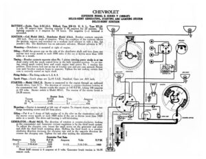
CHEVROLET SUPERIOR MODEL K SERIES V (1926-27) DELCO-REMY GENERATING, STARTING AND LIGHTING SYSTEM DELCO-REMY IGNITION BATTERY.—Exide, Type 3-XC-13-1. Willard, Type XW-13. U. S. L., Type XY-13. 6 volt, 90 ampere hour. Starting capacity is 98 amperes for 20 minutes. The lighting capacity is 5 amperes for 18 hours. The negative (—) terminal is grounded. IGNITION.—Coil Model 284-L. Distributor Model 374-A. Breaker contacts separate -030 inch. They are made of tungsten. When the condition of the contacts affects the ignition, remove and resurface on a medium hard oilstone or with a fine, flat jeweler’s file. The distributor has no automatic advance. Manual advance is 30°. Mounting.—Distributor is mounted at right of engine. Oiling.—Refill the grease cup on the side of the distributor shaft and turn down one quarter turn every month or each 1000 miles if the car is driven more than 1000 miles in a month. Timing.— Breaker contacts separate when No. | piston entering r stroke is at top dead center with the spark control lever in the fully retarded position. To set tim- ing, retard spark control lever and crank engine until piston No. | reaches this position. Then loosen lock nut on top of breaker cam and pry cam upward. Rotate cam until breaker contacts begin to separate. Tighten the nut making certain that cam is correctly seated on taper shaft. Firing Order.—The firing order is 1, 2, 4, 3. Spark Plugs.—Spark plugs are 74-18 S.A.E. Standard. Gaps are .025 inch. STARTER :—Model 710-C, D. Starter is connected to the engine through an outboard Bendix drive, Type R-11. The direction of rotation is counter-clockwise looking at the commutator end. Starter cranks the engine at 140 R.P.M., taking 100 amperes at 4.8 volts. Starter switch is Model 405-C. The tension of the starter brush is 24-28 ounces. Starter Data E Volts Amperes Mounting.—Starter is mounted at left rear of engine. To remove starter, remove two flange mounting screws and lift from place. Oiling.—Put 4 or 5 drops of light engine oil in the oiler on the commutator end of the starter every month or each 1000 miles if the car is driven more than 1000 miles in a month. The drive end bearing is self-lubricating. GENERATOR.—Model 943-B. The direction of rotation is counter-clockwise, looking at the commutator end. Generator current regulation is by the third brush system. To adjust the charging rate, loosen the small screw on the generator end plate and shift the third brush mounting plate. Shifting the third brush in a counter- clockwise direction increases the charging rate and in the opposite direction de- creases the charging rate. Tighten the nut after making the adjustment. Generator Test Data Amperes Volts if Be beeen VDT OD ssn scsscecses 1800 Amperes y femenrtereres 15-17… I Shunt field current is 6 amperes at 6 volts. Generator brush tension is 16-18 ounces each. DIMMER RESISTANCE TAIL LIGHT. STOP LIGHT LIGHTING AND IGNITION SWITCH SIDE LIGHT GENERATOR a — – > G IN DASH LAMP SWITCH BATTERY ¥ O BREAKER (e) Ge la) O “| & | WON? ! ory sy Fd Wining [: Hi = SIDE LIGHT IGNITION COIL Way STARTER aa, a : re uf EN — / ed 7 ‘ z — ‘ XQ ro 4 i) z= aN /* ~~ / My, il ; ‘ / T Lv > OO ammeter SWITCH _ see oats < (a) pir a! STARTING SWITCH NJ CHEVROLET SUPERIOR MODEL K SERIES V (1926-27) REMY GENERATING, STARTING AND LIGHTING SYSTEM REMY IGNITION Mounting.—Generator is mounted at left of engine by special mounting. To remove, remove special clamp screw and swing generator toward engine block. Slip off generator drive belt. Then remove two mounting screws and lift generator from place. Oiling.—Put 4 or 5 drops of light engine oil into generator oiler every two weeks. If car is driven over 500 miles in two weeks, this attention must be given every 500 miles. RELAY.—Model 265-B. Relay is mounted on top of the generator. Relay contacts close at 6-10 M.P.H. or 650 R.P.M. of the generator when the voltage reaches 7.25 volts and open with a discharge current of 0-2.5 amperes. Contacts separate .020 inch. Air gap between relay armature and coil core is .016 inch, contacts closed. Charging current at closing of contacts is 1-3 amperes. LIGHTING:—Clum Switch Model 10633. Head lamps are 6-8 volt, 21 cp S.C. Dim- ming is by resistance on switch. Side lamps are 6-8 volt, 3 cp. S.C. Dash and tail lamps are each 6-8 volt, 3 cp. S.C. Stop lamp is 6-8 volt, 15 cp. S. C. FUSES.—Lighting fuse on back of switch is 20 amperes.