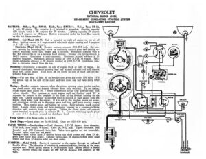
CHEVROLET NATIONAL MODEL (1928) DELCO-REMY GENERATING, STARTING SYSTEM DELCO-REMY IGNITION BATTERY :—Willard, Type XW-13. Exide, Type 3-XC-13-1. U.S.L., Type XY-13, 6 volt, 13 plates. The negative (—) terminal is grounded. Starting capacity (20 minute rate) is 98 amperes for 20 minutes. Lighting capacity (5 ampere rate) is 5 amperes for 18 hours. Battery is mounted under the front floor boards on the left frame member. IGNITION:—Coil Model 284-W. Coil is mounted on right of engine on top of oil filter. Ignition current is 2 amperes at 6 volts with engine running and 4 amperes at 6 volts with engine stopped. Distributor Model 635-B. Breaker contacts separate .018-.024 inch. Set con- tact opening by loosening lock screw on stationary contact plate and turning ec- centric adjusting screw until proper gap is secured. Resurface contacts with a fine flat contact file or on a medium hard oilstone. Breaker arm spring tension is 14-21 ounces. Distributor is semi-automatic. Maximum manual advance is 25 degrees (engine). Automatic advance begins at 1000 R.P.M. of engine. Max- imum automatic advance is 20 degrees reached at 2400 R.P.M. Distributor rota- tion is clockwise viewed from the top. Mounting :—Distributor is mounted on side of engine block at right of engine. To remove distributor, disconnect primary lead and manual advance rod and remove head with cables intact. Then back off set screw on side of shaft and lift dis- tributor from place. Oiling:—Put one drop of light oil on breaker arm pivot pin every 500 miles. Fill a grease cup on the side of the shaft and turn down one half turn every 1000 miles. Timing:—-Breaker contacts separate when the piston entering power stroke reaches top dead center with the manual advance lever fully retarded. To set timing, crank engine until piston No. | enters compression stroke (the upstroke with both valves closed). Then continue to crank engine until the flywheel mark ‘25’ is opposite the pointer in the peephole in the front of the flywheel housing on the right side. Check distributor to see that rotor is pointed at right angles from the engine block away from the engine. If it is not in this position loosen set screw, pull distributor straight up to disengage gears and turn until rotor reaches proper position. Then remesh gears and tighten set screw. Fully advance spark control lever. Loosen clamp screw and turn distributor housing in a counter-clockwise direction until contacts begin to separate. Tighten the clamp screw and connect outer terminal to spark plug in cylinder No. 1. Connect remaining spark plugs in order 2-4-3 clockwise around the distributor head. Firing Order: —The firing order is 1-2-4-3. Spark Plugs:—Spark plugs are 74-18 S.A.E. Gaps are .020-.030 inch. VALVE Ni ihc pare gr eat diameter, 121/32 inches; stem diameter, /16 inch; stem length, 4 inches. Valve lift, 9/32 inch. Tappet clearance, .006 fant) and .008 (exhaust) inch, hot. Valve stem guides are not removable. ersize valve stems are not made. iming:—Inlet valves open 7 degrees before top dead center and close 75 de- grees after lower dead center. Exhaust valves open 56 degrees before lower dead center and close 32 degrees after top dead center. STARTER :—Model 710-D. Starter is connected to the engine through an outboard Bendix drive. The direction of rotation is counter-clockwise, looking at the com- mutator end. Brush spring tension is 24-28 ounces each. Starter switch is Model on Starter cranks the engine at 140 R.P.M. drawing 100 amperes at 4.8 volts. CHEVROLET NATIONAL MODEL (1928) DELCO-REMY GENERATING, STARTING SYSTEM DELCO-REMY IGNITION Starter Data Torque R.P.M. Volts Amperes sr 7 ae ee on 50 TQ: So cocesencesessescecsesscl Lock……….eceeseeeeeeeeee BED eo yeceasteccosessases 450 Mounting:—Starter is flange mounted at left of engine on forward side of flywheel nousing. _To remove starter, disconnect cable and remove flange mounting cap screws. Then pull starter forward and lift from place. Oiling:—Put 4 or 5 drops of light oil in the oiler on the commutator end of the starter every 500 miles. The drive end bearing is oilless. GENERATOR:—Model 943-B. The direction of rotation is counter-clockwise, looking at the commutator end. Generator current regulation is by third brush shunt field. To adjust generator output, loosen small round headed screw on generator end plate and remove cummutator cover band. Then shift third brush in a coun- ter-clockwise direction to increase the charging rate and in the opposite direction to decrease the charging rate. Tightem the screw after making the adjustment With standard car setting maximum charging rate is 18 amperes (cold) reached at 2100 R.P.M. or 25 miles per hour. Generator Data Cold Test Hot Test Amperes Volts R.P.M. Amperes Volts 14-16… Be ccssccn cc! 1700 12 7.5 Shunt field current is 5 amperes at 6 volts. Brush spring tension is 16-18 ounces, Mounting:—Generator is mounted at left front of engine by special swing mounting and is driven by the