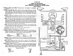
COLE MODEL 8-90 (1923-24-25-26) NORTHWAY M-309 AND M-311 ENGINES DELCO GENERATING, STARTING AND LIGHTING SYSTEM DELCO IGNITION BATTERY.—Willard, Type SJRN-5, 140 ampere-hour. The negative (—) terminal is ground IGNITION: —Coil Model No. 2127. Breaker contacts separate .018 inch. They are made of tungsten. When the condition of the points affects the ignition, remove and resurface with a fine, flat jeweler’s file or on a medium hard oilstone. The tension of the contact arm spring should be 16-20 ounces. Automatic advance be- gins at 600 R.P.M. and reaches a maximum of 14° at 1600 R.P.M. The manual advance is 22°. Mounting.—Distributor is mounted on a bracket at the rear of the generator, but is driven through a vertical shaft by a pinion and worm on the cam shaft. To remove distributor, loosen the manual advance stop screw and lift the unit from its place. Oiling—Put 8 or 10 drops of light engine oil into the distributor oilers every two weeks. If the car is driven more than miles in two weeks, this care must be given every 500 miles.Apply a small amount of vaseline to the rotor track occasional] during the first 2000 miles. After this, it is only necessary to keep the rotor ack wiped clean with a clean cloth moistened with gasoline. Be sure to wipe it dry before placing rotor track into operation. Repack distributor with medium soft cup grease up to the advance ring and yoke once each season. Timing.—Breaker contacts begin to separate when piston No. | on compression stroke is 1% inches before top dead center, measured on flywheel, spark control lever and breaker assembly in the fully advanced position. Firing Order.—The firing order is IR, 4L, 3R, 2L, 4R, IL, 2R, 3L. Spark Plug Gaps.—Spark plug gaps are .030 inch. STARTER.—Model No. 72 (M-309 engine), 259 (M-311 engine). The starter is con- nected to the engine by a Bendix drive. The direction of rotation is clockwise, looking at commutator end. Starter cranks the engine at 125 R.P.M., taking 40 amperes. The brush spring tension should be 2!/%-234 pounds each. Starter Test Data. R.P.M. Amperes Volts 4500: AQ. s® 6.0 (Lock)………….. 4505008. 2 .:a>.. 3.5 Mounting.—Starter is mounted at the right of the transmission case behind the flywheel. o remove, remove the large pilot screw and four hold-down screws and lift starter from its position. Oiling.—Oilless bearings are used. They require no attention. On the Model 259 starting motor saturate the wick in the oiler on the Bendix gear end of the motor with light engine oil once each year. GENERATOR:—Model No. 153. The direction of rotation is counter-clockwise looking at commutator end. The generator begins to supply current at 7 miles per hour or 500 R. P. M. of armature and reaches its maximum current out-put of 14-16 am- peres at 1400 R.P.M. of the armature or 18-25 M.P.H., car speed in high gear. Generator brush tension should be 114-134 pounds each. Generator Test Data Torque 0 (Running free).. 17.5 Ib. ft Apacs R. P.M. eut: foe 300 14-16 (Max) 1400 11-13 2000 @ iy LI ) aE we Ts SN tf t= AY ‘7 / \ if HW] (@) Wipsenh fe) e) @) COLE MODEL 8-90 (1923-24-25-26) NORTHWAY M-309 AND M-311 ENGINES DELCO GENERATING, STARTING AND LIGHTING SYSTEM DELCO IGNITION To increase the charging rate loosen the two screws holding third brush arm, and move third brush in a counter-clockwise direction (looking at commutator end). To decrease charging rate, move third brush in a clockwise direction. Brush must be reseated after adjusting position. Mounting.—Generator is mounted on a bracket at the front of the engine between the cylinder banks. It is belt driven and carries the fan on its forward end. Fan belt ical not be so tight as to crowd the generator bearings nor too loose. If the enerator turns even a part of a revolution when the ignition switch is turned on, the belt is too loose. To remove generator, loosen the large nut on the mounting post and lift the generator and distributor from the bracket. Oiling:—Put 5 or 6 drops of light engine oil into each of the generator oilers every two weeks. If the car is driven more than 500 miles in two weeks, the oiling must be done every 500 miles. RELAY.—There is no relay. The circuit between the generator and battery is con- trolled by the ignition switch. LIGHTING.—Combination Switch Model No. 1154 is used. Head lights are each 6-8 volts, 21 cp. Auxiliary lights are each 6-8 volts, 4.cp. Dash, dome, corner, and tail lights are each 6-8 volts, 4 cp. CIRCUIT BREAKER:—A vibrating circuit breaker takes the place of fuses. It requires 5 amperes to start this devoice vibrating. While vibrating, the current is 3-5 ame peres.