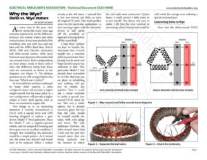
ELECTRICAL REBUILDER’S ASSOCIATION—Technical Document CS201409D www.electricalrebuilders.org Why the Wye? Delta vs. Wye stators BY BOB THOMAS A some time in the past, what now seems like many years ago, someone explained to me the difference between wye-wound stators and delta- wound stators. It was most probably Bob Goulding, who was with Ace, and was later with the APRA. Back then, Delco’s 10DN, 10SI and Chrysler alternators had delta-wound stators, while most Ford and many Japanese alternators had wye-wound stators. Both configurations are three-phase, made of three coils of wire—the difference being how those coils are connected, as shown in the diagrams (see Figure 1). The obvious question on my still-young mind at that time was “Which one is better?” As I was told then and later confirmed by many other sources, a delta- configured stator will provide a higher output overall, but the same stator in a wye configuration will provide a higher output at lower shaft speeds, such as those encountered at engine idle. This brings us to an interesting alternator I recently encountered—a CS121 with a special drive end (DE) housing designed to replace a gear- driven Model T Ford generator. Since the Model T was a negative-ground vehicle, and the unique DE housing and drive gear were in excellent condition, I thought that rebuilding this alternator would be a simple project. As it turned out, the stator was shorted and would have to be replaced. When I looked closely at the old stator, I noticed that it was wye wound, not delta, as were all original CS units. This made perfect sense for this particular application—a slow turning engine with the alternator driven at half speed off the camshaft, as opposed to being driven off the crankshaft. I had three options on how to handle the bad stator. One—I could simply use a standard delta-wound stator that I already had in stock and hope that the output was sufficient at idle. This particular Model T had already been converted to 12 volts. But hope has no place in rebuilding, and nothing will get you in trouble any quicker! Two—I could ask a stator rewinder to make a special wye- wound CS121 stator for me. This was a viable option, but it seemed excessive, given the fact that the coils would be wound exactly the same, both wire gauge and turns. The only difference between the delta-wound stator that I had and the and wye- wound stator that was being replaced, was the manner in which CONNECTOR Figure 2—Separate the lead wires. the coil ends were connected. Option three—I could convert a delta stator to a wye myself. The choice was easy to make. I felt that the time involved in converting what I already had would be DIODES NEG POS WYE-WOUND STATOR AND DIODES Figure 1—Wye-wound and Delta-wound stator diagrams well worth the savings over ordering a special rewound part. Converting Delta to Wye Note that the delta-wound CS121 DIODES NEG POS DELTA-WOUND STATOR AND DIODES Figure 3—Check for continuity. An ERA Publication. ©2014, Electrical Rebuilder’s Association. All rights reserved. No portion of the guide may be reproduced in any way, or stored in any electronic retrieval system without the prior written consent of the Electrical Rebuilder’s Association. Page 1 ELECTRICAL REBUILDER’S ASSOCIATION—Technical Document CS201409D www.electricalrebuilders.org stator has three leads, each comprised of wire ends from two different coils twisted together. Step 1—Separate the lead wires. Each coil has two ends. You have three coils and six ends (see Figure 2). Step 2—Check for continuity between the leads to identify the leads of each of the coils A, B and C (see Figure 3). Step 3—Leave one end of each coil (A, B and C) in its original position and twist the other three loose ends together to make the wye connection (see Figure 4). Step 4—Solder the wye connection (see Figure 5). Step 5—Using a small wooden block or dowel rod, position the new wye connection to where it will be out of the way and cannot short to ground (see Figure 6). Step 6—Add some _heat-proof covering to the three remaining leads and to the new wye connection (see Figure 7). As you can see, this was an easy job that anyone could do. Figure 4—Twist the three ends together. Figure 5—Solder the three ends. Figure 6—Bend the new connection down. Figure 7—Insulate wye connection and leads. An ERA Publication. ©2014, Electrical Rebuilder’s Association. All rights reserved. No portion of the guide may be reproduced Page 2 in any way, or stored in any electronic retrieval system without the prior written consent of the Electrical Rebuilder’s Association.