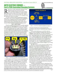
ELECTRICAL REBUILDER’S ASSOCIATION — Auto Electric Corner 2020 _03 AUTO ELECTRIC CORNER — ight when we felt comfortable, thinking we had figured out all of the intricacies of Ford’s PCM-controlled charging system, they modified the system, made it a lot more complex and left the whole thing for the aftermarket to figure out – whose electronics work, or do not, and if they are compatible with the framework of their new system. All of this transpired without publishing any detailed information, short of some rudimentary service guidelines used for basic troubleshooting to be mostly performed using Ford’s IDS, the dealer type scan tool. Thus Iam dedicating this column exclusively to the earlier and later versions of the Ford PCM-Controlled charging system. Part-1 Early Version What we consider to be Ford’s PCM-controlled charging system used to be called System-4 by Ford in some of their earlier publications. It consisted of an alternator (usually a 6-G) whose regulator pins were called A-Sig-Fr (see Figure 1). This arrangement first appeared on the 1999 Windstar minivan as well as the imported Ford Focus, but it gradually propagated through the entire line of Ford products with some minor exceptions. Some people called it the Smart Charging System then, but that was a euphemism that to the best of my knowledge was not used by Ford at that time. Figure 1 – Ford PCM-Controlled Alternator Plug (#337) In this system, the PCM had two lines of communication with the regulator, one to command it to set the charging voltage setting via Sig (or RC for Regulator Control) and second, to monitor the regulator’s duty cycle via Fr (or LI for load indicator). Those parameters of the PCM that were/are accessible via appropriate scan tools and were commonly named GenCom (Generator Communication) and GenMon (Generator Monitor). Different scan tools used slightly different terminology and the way the PID’s Ford’s PCM-Controlied Charging Systems www.electricalrebuilders.org Ford’s System-4 GenCom “Sig”… RC” SCP or CAN Bus Alternator [pcm GenMon 7ER” Li” Figure 2 – Ford PCM-Controlled Arrangement in System-4 (Parameter Identifications) were presented, but nevertheless, they all meant basically the same thing (see Figure 2). There are two main features associated with the System-4 PCM-controlled charging system. The first is a “Default” feature that takes over if the PCM detects anything wrong with any of the alternator communication lines. When that happens, the regulator will default to 13.5V and the charging system warning light (BAT light) is turned on. This feature also allows the alternator to self-excite on the test bench (or on the vehicle) if it is mechanically OK, has a functioning regulator, and is spun fast enough, even with no regulator plug attached to it. The 13.5V default voltage was later changed to 14V setting in most applications. The other feature was the operation of the warning light that was completely independent from the alternator. If the system was working correctly and the PCM was sending the desired command (Sig) and received the proper feedback (Fr), it would put information on the SCP bus that stands for Standard Corporate Protocol, which is Ford’s name for their medium speed communication bus. That later was replaced by the CAN bus which is the higher speed communication bus, mandated since 2008. The PCM’s information will travel thru the bus, reaching every module. The instrument cluster decodes the information and turns the warning light ON or OFF depending on the information on the bus. The alternator has no direct say in this part of the operation and has no connection to the cluster or warning light. Testing this alternator requires a special test-box that can simulate the PCM’s command signal and look at the feedback to determine they are all there. Gradually all the major aftermarket regulator and test lead suppliers came up with such boxes with variable levels An ERA Publication. ©2020, Electrical Rebuilder’s Association. All rights reserved. No portion of the guide may be reproduced in Page 1 any way, or stored in any electronic retrieval system without the prior written consent of the Electrical Rebuilder’s Association. ELECTRICAL REBUILDER’S ASSOCIATION — Auto Electric Corner 2020 _03 www.electricalrebuilders.org AUTO ELECTRIC CORNER of complexity, enabling rebuilders the capability to test these alternators. The aftermarket regulators went through some changes also. Some of the very early versions would work but its operating parameters where not within the limits that the PCM was programmed to see, thus the charging voltage could be 14V but the warning light would not go off unless you used an OE regulator. This gradually got ironed out and most of the name-brand aftermarket regulators now do function properly and do turn the light off. During the years I have repeatedly talked about the operational details of this system with scope captures and DMM readings showing detailed specifics in various seminars. With the number of questions that come through the ERA Help-Line, I feel Iam compelled to briefly explain the details of the system during the upcoming ERA Show in Cincinnati as a refresher to make sure that we are all on the same page. Part-2 Latest Version Obviously, the PCM control of the charging voltage in the above system was not enough for Ford, and a move to a newer and a much more complex system was inevitable. As it has been done by other manufacturers such as GM, Nissan, Hyundai/Kia; a more precise monitoring and adjusting of the regulator’s setting is the trend that is being followed by many. So the new Ford PCM charging system that started showing up in parts around 2012-2013 not only maintains the features of the previous one that we were all becoming familiar with, but also incorporates a few added current sensors to the system that involves other modules such as the ae | SIG RTN 5: VREF Generator Alternator) Current Sensor sci § HTC + | GEN RC tes: CAN – 1 12 | GENLI HS3 CAN + | LIN =| bata —tr HS1 CAN + HS3 CAN – ipo» — te a] | HS1 CAN – SIG RTN Instrument Panel Cluster (IPC) BCS2 ALT Powertrain Control Module Figure 3 – Newer Version of Ford Charging System Components BCM for more precise control of the charging voltage. A general layout of the components involve in this system (see Figure 3) starts with the alternator that interacts with all of these other components. They are: e A Battery Current Sensor e An Alternator (generator) Current Sensor ¢ A Battery Monitoring Sensor (2.7L w/Twin Turbo) ¢ The Body Control Module BEM ¢ The Powertrain Control Module e The Instrument Panel Cluster (IPC) Various vehicle models have a combination of the above modules and sensors but not necessarily all of them in every application. Figure 4 shows a Battery Current Sensor attached to the negative battery cable. Figure 5 shows the Alternator (Generator) Current Sensor attached to the alternator output cable. The system uses the information from these sensors to determine when load-shedding is required and Figure 6 shows the Battery Monitoring Sensor on the 2.7L engines that were equipped with twin turbo-chargers. The system has some similarity to GM’s RVC where various sensors monitor the amount of current going into or out of the battery and then the system, based on the program in the PCM, determines the best system voltage setting, and thus controls the charging rate through a signal to the voltage regulator. The alternators used on recent Fords are usually the Denso SC-type of various output ratings that make use of a 6-G type plug. The pins on the regulator are called BVS (Battery Voltage Sense) – RC (Regulator Control) and LI (Load Indicator). This is a different terminology depicting the A – Sig – Fr of the earlier generation but they serve the same function. The BVS Figure 4 – Battery Current Sensor, attached to Negative Battery Cable An ERA Publication. ©2020, Electrical Rebuilder’s Association. All rights reserved. No portion of the guide may be reproduced in Page 2 any way, or stored in any electronic retrieval system without the prior written consent of the ElectricalPRebuilder’s Association.