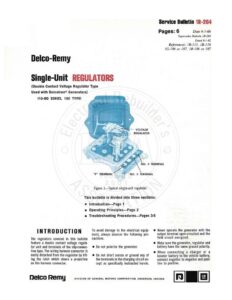
Delco-Remy Single-Unit REGULATORS (Double Contact Voltage Regulator Type Used with Delcotron® Generators) {10-RD SERIES, 100 TYPE) VOLTAGE Figure 1—Typical single-unit regulator. REGULATOR Service Bulletin 12-264 Pages: 6 Date 4-1-66 Supersedes Bulletin 1R-264 Dated 6-1-62 References: 1B-115, 1B-116 1G-186 or 187, IR-186 or 187 This bulletin is divided into three sections: e Introduction—Page 1 e Operating Principles—Page 2 e@ Troubleshooting Procedures—Pages 3-5 INTRODUCTION The regulators covered in this bulletin feature a double contact voltage regula- tor unit and terminals of the slip-connec- tion type. The wiring harness connector is easily detached from the regulator by lift- ing the latch which clears a projection on the harness connector. To avoid damage to the electrical equip- ment, always observe the following pre- cautions. ® Do not polarize the generator. ® Do not short across or ground any of the terminals in the charging circuit ex- cept as specifically instructed herein. @ Never operate the generator with the output terminal open-circuited and the field circuit energized. @ Make sure the generator, regulator and battery have the same ground polarity. @ When connecting a charger or a booster battery to the vehicle battery, connect negative to negative and posi- tive to positive. Neico Remy DIVISION OF GENERAL MOTORS CORPORATION, ANDERSON, INDIANA | |] REGULATORS 1R-264 Service Bulletin BATTERY JUNCTION BLOCK REGULATOR VOLTAGE REGULATOR GENERATOR Figure 2—Typical wiring diagram showing internal circuits. OPERATING PRINCIPLES A typical wiring diagram showing internal circuits of the regulator is illustrated in Figure 2. Following is a brief description of the operating principles of the units in this type of circuit. When the switch is closed, the generator field winding is connected directly to the battery. This allows field current to flow from the battery to the regulator No. 3 terminal, through the volt- age regulator lower or series contacts to the regulator “F” terminal, and then through the generator field winding to ground. When the generator begins to operate, a.c. voltages are generated in the stator windings, and these voltages are then changed or rectified to a d.c. voltage which appears at the “BAT” or output terminal on the generator. Page 2 As the speed of the generator increases, the voltage at the “BAT” terminal of the generator also increases. This impresses a higher voltage across the voltage regula- tor shunt winding. The increased magnet- ism created by the higher voltage across the winding causes the lower contacts to separate, and field current then flows through a resistor resulting in reduced field current. This reduced field current causes the generator voltage to decrease, which decreases the magnetic pull of the voltage regulator shunt winding. The spring causes the contacts to reclose, and the cycle then repeats many times per second to limit the generator voltage to a pre-set value. As the generator speed increases even further, the resistor connected across the contacts is not of sufficiently high value to maintain voltage control on the series contacts. Therefore the voltage increases slightly causing the upper or shorting contacts to close. When this happens, the generator field winding is shorted and no current passes through the winding. With no current in the field winding, the gen- erator voltage decreases, which also de- creases the magnetism in the shunt wind- ing and the upper or shorting contact points open. With these points open, field current flows through the resistor and the field winding. As the voltage increases, the contacts re-close. This cycle then re- peats many times per second to limit the voltage to a pre-set value at high gen- erator speeds. The voltage regulator unit thus operates to limit the value of voltage throughout the generator speed range. Consequently the electrical accessories are protected from high voltage. REGULATORS Service Bulletin 1R-264 TROUBLESHOOTING PROCEDURES (Close adherence to the following procedures in the order presented will lead to the location and correction of charging system defects in the shortest possible time. Only a portion of these procedures need he performed. It will never be necessary to perform all the procedures in order to locate the trouble.) GENERATOR REGULATOR Figure 3—Typical wiring diagram showing basic lead connections. A typical wiring diagram showing basic Trouble will usually show up as an under- cranking, or an overcharged battery as lead connections is shown in Figure 3. charged battery as evidenced by slow evidenced by excessive water usage. A. UNDERCHARGED BATTERY This condition can be caused by one or 2. Defective Battery: If a defective bat- on connectors at the generator, regu- more of the following conditions. tery is suspected, check per Delco- lator, and through the firewall. Check Remy Service Bulletin 1B-115 or 1B- _the wiring harness for grounds. Insure 1. Loose Generator Drive Belt: The gen- 116. that the regulator is properly grounded. erator drive belt should be tightened in 3. Poor Circuit Connections: Visually in- Clean the battery posts and cable accordance with engine or vehicle man- spect all connections to make sure they clamps. Also, make the following tests ufacturer’s recommendations. are clean and tight, including the slip- with switch on. Page 3