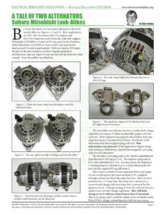
www.electricalrebuilders.org e aware that there are two Subaru alternators that look exactly alike (see Figures 1, 2 and 3). Their applications are 2011-2013 Foresters with 2.5L engines and 2012-2014 Imprezas and Crosstreks with 2.0L engines. Mitsubishi A2TLO091 or Lester 11579 was used on the Foresters while Mitsubishi A2TL0291 or Lester 11631 was used on the Impreza and Crosstrek applications. Both are rated at 125 amps. Except for the part numbers on their original equipment identification tags (see Figure 4) you can not tell one from the other visually. Even the pulleys are identical. Figure 4 – The only visual difference between the two is their ID tags. Figure 1 – From the front, these two alternators look like identical twins. Figure 5 – The regulators appear to be identical but note the different part numbers. The only difference between the two is inside their voltage regulators (see Figure 5) which incidentally appear to be the same too. Both regulators incorporate the familiar three-pin plug that was first introduced by Denso. Previously, both alternators had been assigned plug code 325. That information was incorrect. With input from Regitar along with testing by Mobiletron, Apptrak has assigned a new plug code for each alternator. The Forester’s new plug code is 915 which is identified on that alternator’s ID tag as C-S-L. The Imprza’s plug code is 9151, also identified as C-S-L. In some places, the Impreza’s C terminal may be referred to as G to help differentiate the two, but the original ID tag will show C. — , =| The S and L on both of them represent Sense and Lamp. < j i As you would expect, the sense terminal is B+, supplied € | through a fused wire from the main fuse box. That circuit is protected by a 7.5 amp fuse. The lamp wire connects to a conventional charge indicator lamp that is powered by the ignition circuit. Voltage coming in from the indicator lamp is used to turn on both voltage regulators. They will both Fi 3_ Th d housi Il charge at 14.5v with no connection to their C terminals. gure > ¢ front and rear OUSINGS, PUlreys, rotors, stators, That is by design and it could be called a form of default mode. rectifiers and hardware are all identical. If the PCM’s voltage control function fails for any reason, An ERA Publication. ©2018, Electrical Rebuilder’s Association. All rights reserved. No portion of the guide may be reproduced in Page 1 any way, or stored in any electronic retrieval system without the prior written consent of the Electrical Rebuilder’s Association. Tea _ | ELECTRICAL REBUILDER’S ASSOCIATION — Technical Document CS201806A www.electricalrebuilders.org ATALE OF TWO ALTERNATORS Figure 6 – The plug code 915 for Lester 11579. these alternators will continue to charge at that Vset (voltage set point). Additionally, if for some reason sense voltage is lost, the regulators will both still function, but at a higher Vset of 15.5v. That is worth knowing should a customer ever complain about or suspect overcharging. Test the regulator’s sense wire for voltage. The 7.5 amp fuse in the main fuse box could be blown or missing. So we are now down to the only difference between these alternators. Both C terminals produce a reference voltage that is “looked for” and modified by the PCM to control Vset. The method of modification is different. The Forester alternator’s regulator produces an open circuit output voltage of around 6 volts. If you operate it with only a voltmeter connected to the C terminal, you should see that voltage. The Forester’s PCM uses a ground through a resistor to change the Vset (see Figure 6). On the vehicle, when the battery is fully charged and electrical loads are light, the PCM grounds the C terminal through a 3.9k ohm resistor. That drops the regulator’s output voltage from 6v to 3.1v which results in Vset of 12.8v. During testing, I applied a ground through a 2.7k resistor, which dropped regulator output voltage to 3.3v. The regulator then lowered the Vset to 13.1v. If this looks familiar, Honda used a similar system in the 1990’s. When testing this vehicle, with no electrical loads, a charge rate of 12.8v could be normal. Turning the headlights on should restore a more normal looking Vset. Both JIMCO and AMFOR supply a test lead to check this function. Each are designed to result in a given Vset. Vensel handles individual rebuilder sales for AMFOR while you can buy direct from JIMCO. If you call, specify the lead by Lester 11579. Using a test lead is the most efficient and accurate method for testing this alternator, but in a pinch, you could use a resistor value in the 2k to 4k range and simply look for a drop in Vset when you connect it between the C terminal and ground. The same cannot be said for the Impreza and Crosstrek alternator – Lester 11631! That alternator uses a PWM (pulse width modulation) signal, created by the PCM on the ground side (see Figure 7). This C terminal has a regulator output voltage of 5.9v which is used by the PCM to create the appropriate PWM signal. With input from a dedicated battery sense, an electrical load sensor and other various parameters, this PCM can change the Vset in exactly the same way that GM did with their RVC alternators dating back to 2004 – over a wide range of Vsets from 12.6 to 15.5 volts. Figure 7 – The plug code 9151 for Lester 11631. This alternator must be tested with a PWM device that operates using the ground side – such as an RVC test box. Simply apply sense and lamp input using your test bench and connect the RVC test box’s control wire to the C terminal pin. Then use GM settings to vary the Vset of this regulator. Warning: If you apply ground to this C terminal, even through a resistor, you will destroy the reference voltage circuit inside this regulator. As a result, the regulator will no longer be able to produce its output voltage. While it will still charge in default mode at 14.5 volts and turn off the indicator lamp normally, it must not be installed on a vehicle. If it is, the PCM will immediately see the lack of output voltage on the C terminal as a defect in the alternator, set a charging system fault code and possibly turn on a check engine warning lamp. You can easily test a suspect regulator by operating it using lamp and sense only, with a voltmeter connected to the C terminal. If you do not see output voltage of 5.9 volts or something very close, then the regulator is defective and should not be used. To test either one of these on your regulator tester, you must apply the correct connection as described above and make four connections to the regulator as shown in the photo (see Figure 8). Notice that the field brush is on the bottom looking down as pictured. The top brush is being held out of the way by a piece of insulated wire. The rest of this alternator is pretty standard for late model Mitsubishi units. There are no soldered connections. Every- thing is held together with #2 Phillips head machine screws (see Figure 9). You will need a good Phillips tip and a lot of patience to get all the screws out intact without damaging the rectifier. The stator (see Figure 10) is double wound and delta configured. Notice the heat transfer compound used on the rectifier’s negative heat sink (see Figure 11). Its large surface area dissipates heat quickly to the rear end frame. Also notice the An ERA Publication. ©2018, Electrical Rebuilder’s Association. All rights reserved. No portion of the guide may be reproduced in Page 2 any way, or stored in any electronic retrieval system without the prior written consent of the Electrical Rebuilder’s Association.