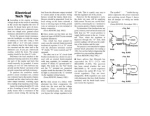
Electrical Tech Tips m™ According to the experts at Jimco, voltage drops are the result of something in the circuit that impedes the flow of current. To locate these spots of resist- ance in a vehicle, use a voltmeter to per- form two simple tests: ground circuit resistance and positive circuit resistance. To test for ground circuit resistance, turn the headlights on while the engine is running at a fast idle. Using a volt- meter with a 1 to 3 volt scale, connect one voltmeter lead to the battery nega- tive terminal and the other lead to the alternator case. If you get a downscale reading, switch the leads. The proper reading should be less than 0.5 volts. Disconnect the lead attached to the alternator housing and move it to differ- ent parts of the engine and body that would normally be grounded. A meter reading of over 0.5 volts between any ground and the battery can mean a bad ground connection and high resistance. To perform the somewhat similar positive circuit resistance test, connect one voltmeter lead to the positive battery terminal and the other lead to the alter- nator output terminal, watching again for a reading drop requiring a lead swap. Again, the reading should be 0.5 volts or less. A reading of over 0.5 volts gen- erally means there is resistance in the positive circuit wiring. By moving the lead from the alternator output terminal to various points in the positive wiring harness toward the battery, likely trou- blespots should be pinpointed. Look for loose wiring on the starter solenoid, a loose or missing engine-to-body ground wire, Or corrosion in a wire terminal or battery connection. (From RENEWS, July 1983.) m@ Jimco points out that there are two electrical types of OEM Toyota external regulator alternators. One, which has been around for years, uses the external fender-mounted mechanical regulator. It is a “B” circuit with the alternator terminals marked “F” (field), “N’ (stator neutral) and “E” (ground). The other one is an “A” circuit (both brushes insulated), has a diode trio and is used with an external fender-mounted solid state regulator. Its terminals are marked “F’” (field), “E” (ground) and “L” (light). The diode trio, the “hot” brush and the “L” terminal are connected together inside the alternator. The indica- tor light is connected to the “L” terminal via the regulator wiring harness. (From RENEWS, January 1982.) m@ The field circuit of a Delco 10S1 alternator has three components: the diode trio, the rotor and the voltage regulator. Jimco recommends that when troubleshooting this alternator you bypass the voltage regulator to the “D” hole. This is a quick, easy way to take the regulator out of the circuit. However, for the alternator to work, the diode trio must still be supplying field current. The trio, too, can be elimi- nated by connecting the no. | terminal to the systems positive (battery terminal). To determine if the brushes/rotor are good, connect your test bench meter and field lead (in “B” circuit position to supply field current) to the no. | termi- nal. Then, when the regulator is bypassed through the “D” hole, field current readings will tell you the condi- tion of the brushes and the rotor. The practice is not intended to replace normal bench procedures for testing a 10S1, but can be a help in diagnosing the problem in a non-working alternator. (From RENEWS, May 1982.) m@ Jimco advises that Motorola has superseded the R7-3 (5-23) with 8RG2009B (5-200). The question has been raised whether the new 8RG2009B (a “B” circuit regulator) can replace the earlier R7-3 (an “A” circuit regulator). They are inter- changeable. Both regulators are used with alternators that have both brushes insulated, and the brush leads termi- nate inside the regulator. The symbol “ ” inside the reg- ulator represents the power transistor and switching circuit. Figure 1 shows that all changes in wiring are inside the regulator. (From RENEWS, November 1981.) + Pos. Red Brush “B” Circuit Rotor 5-200 Regulator – Neg. BLACK + Pos. Red Brush Rotor 5-23 Regulator Brush – Neg. BLACK