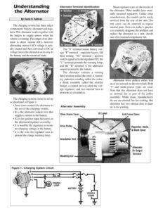
Understanding the Alternator By Kevin R. Sullivan The charging system has three major components: battery, alternator and regu- lator. This alternator works together with the battery to supply power when the vehicle is running. The output of an alter- nator is direct current (DC), however alternating current (AC) voltage is actu- ally created and then converted to DC as voltage leaves the alternator on its way to the battery and the electrical loads. The charging system circuit is set up as illustrated in Figure 1: ¢ Four wires connect the alternator to the rest of the charging system. ¢ B is the alternator output wire that supplies current to the battery. ¢ IG is the ignition input that turns on the alternator/regulator assembly. ¢ S is used by the regulator to moni- tor charging voltage at the battery. ¢ L is the wire the regulator uses to ground the charge warning lamp. Alternator Terminal Identification ‘S’ Terminal ‘L Terminal ‘F’ Terminal ‘IG’ Terminal ‘B’ Terminal The “S” terminal senses battery volt- age; “F’ terminal—regulator bypass, full field testing; “IG” terminal— ignition switch signal turns the regulator ON; the *L” terminal grounds the warning lamp; and the “B” terminal is the alternator output terminal to the battery. The alternator contains a rotating field winding called the rotor; a station- ary induction winding called the stator; a diode assembly called the rectifier bridge; a control device called the volt- age regulator; and two internal fans to promote air circulation. Alternator Assembly Most regulators are on the inside of the alternator. Older models have exter- nally mounted regulators. Unlike other manufacturers, this model can be easily serviced from the rear of the unit. The rear cover can be removed to expose internal parts. However, today’s practice is to correctly diagnose the problem and replace the alternator as a unit, should one of its internal components fail. Alternator drive pulleys either bolt on or are pressed on the rotor shaft. Both “V’ and multi-groove types are used. Note that this alternator does not have an external fan as part of the pulley assembly. While many manufacturers do use an external fan for cooling, this alternator has two internal fans to draw air in for cooling. Drive Frame Cover ID Label Drive Pulley hid Circulation Vent Mounting Ear Figure 1—Charging System Circuit VEHICLE LOADS End Frame Cover Regulator, Diode, & Brush Cover Alternator B+ Output Terminal