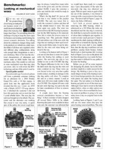
Benchmarks: Looking at mechanical woes COLUMN BY JOEY CLINE or me, one of the greatest things about being an independ- ent business owner of a small electrical rebuilding shop is the everyday chal- lenges that I face. ’’m not talking about the challenge of trying to keep the doors open for business and creating a profit during the current economic downturn. ’m talking about the continuous changes being made in the products we rebuild on a daily basis. Just think of all those new regulator colors and different plug configurations along with enough letter designations to start a new dictionary. Most of the time the elec- trical characteristics of alternators and starters make us think harder than the mechanics does. This month we will look at some mechanical woes that may slow you down. Also we will review the RVC technology and one of the units it’s used in. Special puller needed Several months ago I received a phone call from a potential customer looking for an alternator for a 2004 Pontiac Grand Prix with a 3.8 liter engine. A quick look into the application book revealed that this was Lester no. 8293 with a Delphi AD237 125-amp alterna- tor. I informed the customer I did not have this particular unit in stock but that I could rebuild theirs. The next day the unit was brought in to be rebuilt. The cus- tomer said the alternator was working fine except it was very noisy. A quick spin of the pulley did reveal rough bear- ings. As always, I asked how many miles were on the given unit, and the customer replied 94,000. I gave the customer a price and said the unit would be ready in a couple hours. What’s the big deal? It’s just an AD unit that is very similar to the popular CS130D. The unit was tested first to verify the customer’s claims and then off to the rebuild bench it went. The unit came apart very easily. The rotor was removed from the DE housing in prepara- tion for the SRE bearing to be removed. Now, this is where the process came to a screeching halt. This particular Delphi AD unit utilizes one of the new-style slip rings that are starting to show up in sever- al late model Delco units. It can be iden- tified by the rotor coil wires being sol- dered to the top. Looking at the bottom half of Figure 1 you can see that there is room for a puller under the bearing but nothing to push against. The new-style slip ring is very similar in size as the CS130D slip ring. The biggest difference in the two is that the latest-style slip ring has the rotor coil wires soldered on top. These wires are now located in the very area that a puller would contact, resulting in damage to the slip ring and/or coil wires. To complete this unit in a timely manner I used an older-style AD rotor, made similar to that of a CS130D. The original AD rotor, with the new-style slip ring, was put to the side for later consideration of how to remove the bearing. A couple days later the bearing removal consideration became a “now thing.” A fleet customer of mine dropped off several Delco 24SIs to be rebuilt. Knowing that parts were available for these units now, the customer was informed that we would have them ready in a couple days. Upon disassembly of the units the new-style slip ring was observed yet again. With no spare rotors to grab to bail me out of this situation, I was forced to come up with a way to remove these bear- ings. The lower half of Figure 2, page 18, shows the Delco 24SI rotor. Let’s look at several options for removing the SRE bearing, which is referenced as a 202.When the wires are desoldered and the slip ring is removed, the shaft that is exposed is merely the size of about three toothpicks put together. It would not take much pressure to bend or mushroom the shaft, making it difficult or impossible to re-install the slip ring. If this portion of the rotor shaft is even slightly bent, then the slip ring would have run-out problems causing brush bounce, broken brush leads or short regulator life. Looking back at Figure 2 you can see the plastic fan has been designed in a way under the bear- ing that makes it difficult for any puller to fit under the bearing. Before you go off on some engineer for designing the plastic fan in this fash- ion there might be a viable answer for the design. My thinking is just as they use a metal slinger on top of the bearing to pro- tect it from foreign particles, the close and wide plastic fan under the bearing does the same. The last option is to break the bearing and grind or cut off the inner race. Although I have had to revert to the latter option before, when no other option was available, I have discovered that this bear- ing removal problem is going to be seen many times a day on a regular basis in the near future. Looking back at Figures 1 and 2 you will see two more rotors that have the same bearing removal problem. The rotor _- Bearing Plastic Fan up close te Bearing Coil Wires. Figure 1 Bearing 0.0, Same ae 202 SRE Fan with Shroud around Rotor ,.~ Goll Wires Plastic Fan up