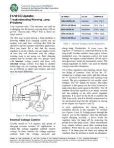
E Technical Document CS201204A = www.electricalrebuilders.org A @. { ‘) ] Produced by the Electrical Rebuilder’s Association Ford 6G Update: Troubleshooting Warning Lamp Problems Your customer calls. “The alternator you sold me is charging, but the battery warning lamp will not go out.” Then he asks, “Why?” Fact is, there’s no single answer. The first step toward solving a lamp problem is knowing which Ford charging system you are dealing with and then verifying that both the alternator and the regulator match the application. Once you know for a fact that the correct regulator is on the vehicle, you can begin a series of tests that will determine why the charge- warning lamp is not going out. Ford charging systems can be divided into two groups: those with internal voltage control and those with external voltage control. You have to identify which type you are working with, because they are as different as apples and oranges, and each must be tested differently. oO on ate® rer? ‘ roo? Gov? . yor Ground cont o re ov? ! 1} | — XXXXXX-100359-XX Stator DIFRIIS a / 4 AlAl Al _| ) / t 7 (upper brush) Figure 1—6G Regulator Plug Codes Internal Voltage Control Usually found on V-8 engines, this group of charging systems includes all applications in which the voltage regulator controls system voltage. In these vehicles the voltage regulator controls both the voltage set-point and OE PART # COLOR TERMINALS F8WU-10C0359- AB Grey/Grey I-D-A_ (Fig. 1) VP3C3U-100359-AA Grey/Green I-D-A_ (Fig.1) XS7U-10C359-AC White/White | LER-A. (Fig.2) X$7U-100359-AC White/Orange | I-FR-A (Fig.2) Black/Black I-FR-A (Fig. 2) Table 1—Internal Voltage Control Regulators VP4L1U-100359-AA charge-lamp illumination. In some cases, the regulator “I” terminal is connected directly to the lamp itself. In other vehicles, more typical in later production years, the regulator controls the lamp through the engine control module (ECM) and a microprocessor inside the instrument cluster. The voltage regulators in Table / are used in internal voltage-controlled alternators. All of these regulators and charging circuits have two things in common. They all use the “A” terminal as a voltage sense point, and they all use the “I” terminal for excitation and warning-lamp control. The grey regulators do not use the center terminal. The “D” stands for dummy. The white regulators in this group use the center terminal to send a field duty-cycle signal to the ECM. The FR terminal (field-rate monitor) is an output terminal and has nothing to do with actual regulator operation. It is used by the ECM to monitor the field duty-cycle, which is directly proportional to the mechanical load that the alternator is placing on the engine (see Figures 3 and 5). In early applications, the charge lamp is connected directly to the regulator “I terminal (see Figures 2 and 3). Voltage passes through the lamp to turn on the regulator. Once the alternator begins charging normally, a driver inside the regulator turns the lamp off by removing the ground from the lamp circuit. These conventional lamp circuits seldom cause false warning-lamp problems. When they do, you can check it fairly easily. If the lamp goes out when you unplug the regulator, then the problem is inside the alternator. Created by Wes Grueninger Sr. and Bob Thomas for the Electrical Rebuilder’s Association. © 2011, Electrical Rebuilder’s 1 Association—All rights reserved. No portion of this guide may be reproduced in any way, or stored in any electronic retrieval system without the prior written consent of the Electrical Rebuilder’s Association. Technical Document CS201204A Produced by the Electrical Rebuilder’s Association www.electricalrebuilders.org & Instrument Cluster Warning I (Ignition) D (Dummy, not used) Fuse (in engine compartment ‘y fuse box) ALTERNATOR BATTERY ®@00000 Positive Negative |-D-A Regulator: = Internal Voltage Control – Lamp Controlled Via Regulator Instrument ECM Cluster (Engine Control Module) I (Ignition) D (Dummy, not used) A (Sense) Fuse (in engine compartment ‘9 fuse box) ALTERNATOR BATTERY @00000 Positive Negative |-D-A Regulator: = Internal Voltage Control – Lamp Controlled Via ECM & Cluster Figure 4— I-D-A, ECM & Cluster Control Lamp Instrument Cluster Warning ECM (Engine Control Module) FR Signal to ECM I (Ignition) FR (Field Rate Monitor) ALTERNATOR BATTERY ©000080 Positive Negative |-FR-A Regulator: = Internal Voltage Control – Lamp Controlled Via Regulator Instrument ECM Cluster (Engine Control Module) FR Signal to ECM —— >> I (Ignition) FR (Field Rate Monitor) A (Sense) ALTERNATOR BATTERY ©000080 Positive Negative |-FR-A Regulator: = Internal Voltage Control – Lamp Controlled Via ECM & Cluster Figure 5—I-FR-A, ECM & Cluster Control Lamp 2 Created by Wes Grueninger Sr. and Bob Thomas for the Electrical Rebuilder’s Association. © 2011, Electrical Rebuilder’s Association—All rights reserved. No portion of this guide may be reproduced in any way, or stored in any electronic retrieval system without the prior written consent of the Electrical Rebuilder’s Association.