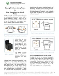
Technical Document MS -0908A Produced by the Electrical Rebuilder’s Association www.electricalrebuilders.org Solving Problems Using Relays Or Four Handy Uses for Bosch Relays A relay is simply an electrical device designed to switch a large amount of current using a smaller amount of current. Some, like the fender-mounted starter relays on Ford vehicles of the 60’s through 80’s, were made to carry several hundred amps for a short duration. Figure 1 — Early (left) and Late (right) Ford Starter Relays Others, like the small Bosch relays, (now manufactured by Tyco), are designed to carry smaller loads of up to 40 amps for unlimited lengths of time and are known as_ continuous duty relays. This article will deal Figure 2 — Mini-Relay with a few common electrical problems you can easily solve using relays. There are many different relays available in the aftermarket, in a variety of amperage and voltage ratings. Many have a mounting bracket built onto the case. The pinout numbers and internal diagrams are usually printed on each relay. The relay shown in Figure 2 is the style most commonly used by rebuilders. It is based on standards set by the International Standards Organization (ISO) and its technical name is ISO Mini-Relay. ISO Mini-Relays are built into a 1” square cube, and the pinouts are standardized as shown in the following diagrams. In the rebuilding industry, ISO Mini-Relays are usually referred to as “Bosch Relays”. SPST RELAY with one #87 terminal 86 Pinouts Schematic Figure 3 —Single- Pole Single-Throw with one #87 terminal SPST RELAY with two #87 terminals 86 Schematic Pinouts Figure 4 —Single-Pole Single-Throw with two #87 terminals SPST (single-pole single-throw) Relay: Terminals 85 and 86 are connected to the coil. Terminal 30 is common and usually connected to B+ through a fuse. Terminal 87 is where the load is connected. When power is applied across the coil, the contacts close to connect 30 to 87. Some relays have two 87 load terminals (Figure 4). SPST relays may have four or five terminals. Created by Wes Grueninger and Bob Thomas for the Electrical Rebuilders Association – © 2008, Electrical Rebuilder’s Association — All rights reserved. No portion of this guide may be reproduced in any way, or stored in any electronic retrieval system without the prior written consent of the Electrical Rebuilder’s Association. Technical Document MS -0908A Produced by the Electrical Rebuilder’s Association www.electricalrebuilders.org SPDT RELAY 86 Pinouts Schematic Figure 5— Single-Pole Double- Throw SPDT (single-pole double-throw) Relay: Terminals 85 and 86 are connected to the coil. Terminal 30 is common and usually connected to B+ through a fuse. Terminal 87 is where the load is connected. Terminal 87 will be connected to 30 when power is applied across the coil. When the relay is inactive, terminal 30 will be connected to 87a. SPDT relays always have five terminals. This type of relay is sometimes referred to as a changeover relay because the current flow changes from terminal 87a to terminal 87 when the coil is energized. RELAY with Spike-Suppression Diode 86 Schematic Pinouts Figure 6 — SPST Relay with Diode Spike-Suppression Diode: When a relay is switched off, the collapsing current in the coil can cause a small voltage spike. If the relay is controlled by a solid-state device, such as the PCM, this spike can cause damage. One method of protecting the relay control circuit is to install a diode in parallel with the coil (see Figure 6). The purpose of the diode is to bleed off voltage spikes generated each time the relay is switched off. If there is no diode connected in parallel with the coil, polarity does not matter. But when a diode is used in the relay, power must be applied to only the negative side of the diode, or terminal 85. The diagram printed on the relay will show a diode if one is used. This isn’t a style of relay that you are likely to buy from any rebuilder supplier, but you should be aware of its existence, especially if you are wiring up a used relay. Hooking it up the wrong way will cause a direct short between terminals 85 and 86. What’s Inside? Contacts ~, Term. 87a Term. 30 Term. 87 Figure 7— What’s Inside a SPDT Relay Created by Wes Grueninger and Bob Thomas for the Electrical Rebuilder’s Association – © 2008, Electrical Rebuilder’s Association — All rights reserved. No portion of this guide may be reproduced in any way, or stored in any electronic retrieval system without the prior written consent of the Electrical Rebuilder’s Association. Technical Document MS -0908A Produced by the Electrical Rebuilder’s Association www.electricalrebuilders.org Problem Fix #1: Low Voltage at Starter S Terminal PROBLEM: There is low voltage at the S terminal of the starter solenoid due to worn contacts or poor connections in the switch circuit. This could be caused by the ignition switch, neutral-safety switch, old harness connections or a combination of more than one source of resistance. Often on older vehicles, the solenoid only clicks. This happens when there is not quite enough voltage at the S terminal to close the contacts every time. SOLUTION: Install a SPST relay to activate the starter solenoid, and control the relay using the original start circuit. The relay needs only a fraction of an amp, so the voltage drop becomes negligible, and full battery power will be applied to the S terminal every time. CAUTION: Be careful not to bypass any safety switches when installing a relay. All neutral-safety switches, operator-present switches, and equipment-disengaged switches should be included. that carry current to the relay terminal 30. BATTERY ©000e08 Positive NOTE: This is a simplified diagram and does not show all circuits present on the equipment/vehicle. Always install a fuse on all circuits STARTER IGNITION SWITCH SPST RELAY Figure 8 — Amplifying “S” Terminal Voltage Created by Wes Grueninger and Bob Thomas for the Electrical Rebuilders Association – © 2008, Electrical Rebuilder’s Association — All rights reserved. No portion of this guide may be reproduced in any way, or stored in any electronic retrieval system without the prior written consent of the Electrical Rebuilder’s Association. 3