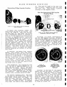
sthat these they are loose BLUE Dismantling F-Type Impulse Coupling ILLUST. 43–F-TYPE IMPULSE COUPLING DISMANTLED FROM THE MAGNETO. To remove the coupling member (8) start puller SE-912 in the threads (See Illust. 39, Item 9), then lock the mem- ber with pawl (7) and screw the puller until considerable effort is required to turn it. If the impulse has been allowed to stand or operate without sufficient oil, coupling member (6) is likely to be rusted and stuck on the shaft. It may be necessary to use two screw drivers, one from each side between the coupling and the magneto frame, and to hit the puller SE-912 a rather hard blow, at the same time exerting pressure on the screw drivers. Care must be used when this condition exists to remove the member without damaging the threads or the mag- neto frame. To separate cam member from magneto member, pull outward until lugs clear, let unwind about one-half turn, and then remove. Drive spring can be easily pried out with a screw driver. In replacing spring, first hook it into position at “B” | being sure it will wind in the dir- ection shown. Wind the spring into po- sition, using the right hand to push it gradually down and the left hand to hold the wound coils in place. When assembling the coupling be sure that the hub of magneto member (6) is clean and well oiled, and if the latch spring (8) is rusty, replace it witha new one. Couplings must be oiled gener- ously with cream separator oil at regu- lar intervals. When the weather is ex- tremely cold, kerosene should be used. The earlier engaging pawls were held on the pawl pin by cotter pins. Be sure cotter pins are tight. If they will soon wear and drop out. Replace these cotter pins if they show any signs of wear. At present snap rings are used to hold these pawls RIBBON SERVICE on. They must be tight on the pawl pins when in place, otherwise they will wear and fall off. This causes a general wreckage of the magneto frame. How the International E4A Impulse Coupling Works ILLUST. 44–E4A IMPULSE COUPLING PARTIALLY DISMANTLED TO SHOW HOW IT WORKS. Following is a brief description of how the E4A Impulse Coupling operates: The coupling member unit (Illust. 44) is locked to the magneto drive shaft and always rotates steadily at engine speed. The magneto member unit is keyed to the armature driving end. These two units are connected to the drive spring as in- dicated in Illust. 44. PAWL) 6g ns 4 y oh a | _-TLLUST, 46 CENTRIFUGAL FORCE HOLDS PAWLS OUT OF ENGAGEMENT AT SPEEDS GREATER THAN 100 R.P.M. i ILLUST. 45 PAWL ENGAGED AND ABOUT TO BE TRIPPED BY LUG “H” ‘ Attached to the back of the magneto member unit are two pawls (Illusts. 44, 45, and 46). When the engine is turning at less than 100 R.P.M., gravity causes the uppermost pawl to catch the coupling plate at “CP”, Tllusts. 45 and 48, in notch “N”, Tilust. 45. This prevents the magneto member from turning until lug “H” of the steadily rotating coupling member trips the pawl by hittingits tail as shown in Illust. 45. INTERNATIONAL E4A TYPE IMPULSE COUPLING In the meantime, the drive spring has been wound up almost one-quarter revolu- tion. Therefore, when the pawl is trip- ped, this spring unwinds, hurling the magneto member unit and rotor rapidly forward. Then, in the next one-half revolution, the second pawl comes to the top, catches, is tripped and the magneto armature is again hurled rapidly forward. Tripping of the pawls is timed so as to cause a spark when engine is on dead center or from dead center to 8° after dead center, provided the magneto is properly timed to the engine. The snubber spring acts as a cushion against the impact of lugs “A” against lugs “B”, Illust. 44, after the magneto member unit and rotor have been hurled forward by the drive spring. Cushioning movement of the snubber spring is limited by lug “L” which fits into groove “G”, Illust. 53. When the engine runs ata speed great- er than 160 to 180 R.P.M., the centrifu- gal effect on the pawls is sufficient to hold them firmly against the inside of the two lugs “H” as in Illust. 46, so that notches “N” fail to catch at “CP”, All parts of the coupling then rotate as a single unit. Dismantling E4A Type Coupling COUPLING COVER FELT COUPLING COVER MAGNETO MEMBER SHAFT SNAP RING, INNER ROTATING UNIT (PARTIALLY REM ILLUST. 47–ROTATING UNIT IS PULLED OFF BY UNSCREWING COUPLING UNIT. 1. Release the two cover springs and remove coupling cover [llust. 47. Exam- ine the coupling cover felt. If a new felt is necessary, remove old felt, clean coupling cover of all dirt, oil and grease and shellac new felt in place. 2. Using a 9/16″ socket wrench, with a socket having an outside diameter of not more than 25/32″, unscrew the coup- ling nut, Illust. 47, from the rotor driving end. While the nut is being un- MAGNETO MEMBER SHAFT SNAP RING, OUTER SOPPLING PEATE MAGNETO MEMBER SHAFT COUPLING OUTER SNAP RING WASHER PLATE j . < 63 NGTE POSITION OF MOTCHES ROTATING UNIT (cs) e ILLUST. 48--ROTATING UNIT AND COUPLI