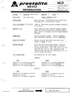
Printed in U.S.A, ©, prestosite___ M.D __ SERVICE Traction Hotor Page 1 of 2 INFORMATION _sRevised ayi/s8 VOLTAGE 12 ROTATION Reversible BRUSHES 4 POLES 4 VENTILATED See Tabulation . FRAME DIAMETER 6-5/8″ LUBRICATION None required. Prelubricated and sealed ball bearings used at both ends of motor. FIELD RESISTANCE (77°F/25°C) .0062 to .0070 ohms measured between terminals S-l and S-2. ARMATURE TEST These armatures have standard winding connec- tions and can be tested on a growler using a metal strip or hacksaw blade to locate shorted windings. COMMUTATOR Minimum diameter 2.875″. Replace armature when commutator has worn to this dimension. BRUSH REPLACEMENT Replace brushes when they have worn to a length of 9/16″ or less. SPRING TENSION 30 to 36 ounces with new brushes. Measure with a spring scale hooked under the brush spring at the brush. Pull the scale on a line opposite the line of force exerted by the brush spring and take the reading just as the spring leaves the brush. TEST CONNECTIONS See tabulation for test number. TEST #1 CWDE CCWDE Connect S-1 to battery positive Connect S-1 to battery positive Connect S-2 to A-1 terminal Connect S-2 to A-2 terminal Connect A-2 to battery negative Connect A-1 to battery negative TEST #2 CWDE CCWDE Connect A-1 to battery positive Connect A-1 to battery positive Connect A-2 to S-2 Connect A-2 to S-1 Connect S-1 to battery negative Connect S~2 to battery negative L-600 SERVICE MANUAL _—> TRACTION MOTOR MLD Continued 7 Page 2 of 2 SERVICE Rev: 4/1/88 INFORMATION TEST SPECIFICATIONS (77°F/25°C) Test in both directions of rotation. Terminal Maximum Torque Voltage Amperes RPM Ft. Lbs. No Load Test 12 30 3300 0 Light Load Test 10.68 70 1590 to 1770 2 INTERNAL TEST UNIT WIRING VENTILATED CONNECTIONS MLD-4001 Figure 1 Yes #1 MLD-4002 Figure 1 Yes #1 MLD-4003* Figure 2 Yes #2 MLD-4004 Figure 1 Yes #1 MLD-4005 Figure ] Yes #1 MLD-4006 Figure 1 No #1 MLD-4007 Figure 1 No #1 MLD-4008 Figure 1 Yes #1 MLD-4009 Figure 72 Yes #2 MLD-4010 Figure 1 Yes #1 * Note: This motor can operate at 12 or 24 volts. VIEWED FROM COMMUTATOR END VIEWED FROM COMMUTATOR ENG FIG. 1 FIG. 2