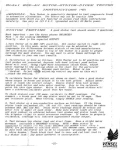
RAC ee Z RED-AY REOT OR DTA TOR-DPLODLT TEA CES? ~ 7 LIN DT ILRI OS I OIE —(* 6D) VhINEIA¢ This Tester is especially designed to test: components pound in automotive alternators. The Tester may not be exactly like equipment with which you are familiar so please read these instructions carefully. Use anly on 115 V.A.C. (grounded outlet) 60 Hertz power. er ee ne ee STATOR WESTING A good stator test should answer 3 questions. Most important — are the three phases BALANCED? Next – is the wrading GROUNDED? Finally — what js the expected OUTPUT? 1.Turn Tester on to RSD (UP) position. Set center switch to right (AC) position. In this mode, meter sensitivity can be adjusted to compensate for differences batween stators of varjous manufacturers. Vs The calibration:chart found an top of the Tester is a quide to proper settings for mast stators. You may want ta alter these settings to come closer to your own test results. @. Calibration ax done as follows: With Tester set ta AC position and test probes nat. iPannected, depress left-hand (stiver) push button. Meter will read.: Using right-hand adjustment (black knob), adjust : meter reading td the setting shown on the chart for the particular Me stator you want | ite test… Release push button. Meter is now librated. Da ‘hot touch adjusting control any more as this will w.sturb the setting. To calibrate Tester fer stators not shown on chart, take a goed stator whose output is:-known and attach it to the test probes. Adjust meter. unt?] tt reads the correct output. Remove stator from test prabes. depress push button and note meter reading. this is the calibrate point fer this type stator. Write it down! Delta wound stators will have a different: calibrate point than Wye wound. To check stators: over 120 amps. calibrate to HALF readings. For 7 examplé — a knewn good 140 amp stator would be set ta 7@ amps. Then : get calibrate Pepat. When testing, Simply DOUBLE your reading. 3. Test stator on a& non-conductive surface as follows: If the three stator leads areimarked (A), (B) and (C), test readings should he taken between A&B, BEC: and A&&. These three readings should be within one méter line (2 amps) of each other. Make sure stator leadg are clean and good contact is achieved batween test probes and stator leads (use the aligator clips) to avoid erroneous readings. If tester is properly calibrated, readings will indicate approximate stator output, 4. Test between ‘any Stator lead and steel frame. Even a slight meter faovement indicates a GROUNDED winding. NOTE ~— When stator is connected to dindes Cin the casa) BALANCE snd QUTPIST tants Catep 2 above) are performed ag outlined ahove. The’ GROUND test, huwever, must be done with the: Tester set to DC ta eliminate “yreunding” by the Cative diodes. | Touch black test lead to case and red test lead to auy Stator lead.i: Any meter mavement is unacceptable. “01- VENSEL ENTERPRISES rem tt NEW Engrs. Co. SBs29g507T2Z2 P.@2. 2OTOR THSTITNG To test alternator rotors, proceed ag follows:. 1. Set left hand (on-off) switch UP which turns Tester on te its RSD ret ion. Pilot light and RED and GREEN polarity lights should come aon, He sure tect lead probes are not shorted together. 2. Set center aniten to its left (DC) pesition. Red probe is POS. Black probe fs NAG. 3. Touch test probes to the two rotor slip rings (etther probe to either ring) and note meter reading. This reading (on the Q-1? amp Scale) tndicates the current draw (from al? volt battery) for the rotor under test. Normal readings will fall in the 2-6 amp range. Higher readings ‘usually denote stronger rotors. Determine your own (GO) and Sila’ “specs for each type roter by testing a group of the same rotars. Current ruadtusch wien indicate rater resistance (ohms) indirectly as follows: OHMS #1) 12 divided by AMPS, AMPS 2.6: 2.5 3.0 3.5 4.0 4.5 5.0 5.5 6.0 OHMS 6.G 4.8 4.0 3.4 3.0 2.7 2.4 2.2 2.0 4. Touch one prabe to either slip ring and the other probe to the rotor Shaft. Even a slight movement of the meter denates a grounded winding. } : When testing 24 volt rotors, double meter reading to get tru? amp draw. en et a ne ee i en ne ne i a J? TODS, PRS IO LING This test determines if the diode is ~~ Forming its norma 1 duty by rectifying an AC signal. Set an-off ~ stch ta up (RSP) position. Set center switch ta right (AC) pasition. Connect a “known:good” power diode to the test leads and set meter to center scale (60). To test other diodes, (remove aligator clips) touveh black test prabe’to diode body or metal frame (heat sink) in which divude is mounted; Touch red test probe ta diade pigtail or copper strap. A good positive diode will cause meter to deflect to 60 and the green polarity light to go out (red light stays on). A gvood negative diode will read 60 on the meter and cause the red light to go aut (green light stays on). An OPEN Qdiore will cause ne meter deflection while a SHORTED diode results in full scale deflection. Stator leads need not be disconnected for diode testing. When cannected ta the stator RAPES Py), aR ar an open diode will read abaut 45 an the meter instead of zera.’; When testing small dicedes (trias, etc.) limit test time to 5 seconds. Diede tries can algo be tested without disconnecting. RICHARD & BARBARA VENSEL (815) 459-0355 (800) 662-6099 3710 RIVERSIDE DRIVE CRYSTAL LAKE, ILLINOIS 60014 USA FAX (815) 459-0442 ‘ VENSEL