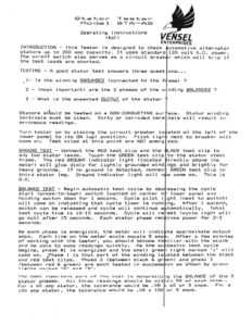
Tester STA—-AS Stkatrior Mocdel Operating Instructions (K&F) ENTERPRISES INTRODUCTION – This Tester is designed to check stators up to 200 amp capacity. It uses standard Tha on-off switch also serves as a circuit break the test leads are shorted. TESTING – A good stator test answers three quest pit Is the winding GROUNDED (connectad to the Ff 2 – (most important) are the 3 phases of the w 3 – What is the expected GUTPUT of the stator Stators sHould be tested on a NON-CONDUCTING sur terminals must be clean. Dirty or corroded term erroneous readings. Turn tester on by placing the circuit breaker lo lower panel to its ON (up) position. Pilot ligh come On. Test clips at this point are NOT energ GROUND TEST – Connect the RED test clip and the any two stator leads. Touch the GREEN test clip frame. The red GROUND indicator light (located meter) will glow dimly for lightly grounded wind heavy grounds. If no ground is detected, connec third stator leg. Ground indicator light will n O.K. Se ee ge ee re start (press—-to-test) switch loacted at center o holding switch down for 1 second. Cycle pilot 1 will come on indicating that cycle timer is runn Switch can be released and cycle will continue a test cycle time is 10-12 seconds. Cycle will re go out) after 15 seconds. seconds. As each phase is energized, the meter will indic amps. Each line on the meter scale equals 5 amp of working with the testor, you should becomes fa and be able to make readings quickly. As the au begins, phase #1 is energizad and the small gree Gome on. Phase 1 is that part of the winding lo and red test clips. Phase 2 (between black & gr (between red & green) are each tested in success Pighta merkoad “RB” amd ME”. impertant part of the tost is determini All three readings should be wit the tolerance would be .0O5 «O35 x 100 The most Stator phases. For a 60 amp stator, 100 amp stator, the tolerance would be Each stator phase rec utomotive alternator 120 volt A.C. power. r which will trip if ONS. «a. ame) ? Stator windirg im ace. nals will resutt ated on the left af the next to breaker will zed. LACK tast clip to to the stator steel irectly above he ngs and brightly for GREEN tart clip te w come on. This ie essing the cycle lower panel and ght (next to switch) nge After 1 second, tomatically. Total set (cycle light will ives power for 2-3 te approximate output « After a few minutes iliar with the scale Omatic test cycle light marked “i” will ated between the black en) and phase $ on as shown by green a the BALANCE of the 3 in S% ef each athe. 60 or 3 amps. For a or 5 amps. A word about HEATING. This tester is not just a instrument. Tt puts a heavy A.C. Current throug tested in order to heat the windings to expose b heating effect has several consaquences….. 1 —- Coils get HOT! Re careful not to burn y On Or near paper or other flammable material 2 —- Repeated tests could damage the winding. cooling, the windings may be damaged by exce testing to 2 consecutive cycles. Allow stat before re-testing. 3 – As a winding heats up, its resistance wi – meter reading will drift lower. During the test sequence, this will cause a 100 amp ini abdt 98 amps. This is normal and still well tolerance range. On DELTA wound stators, th reading dropping to 98 amps) will repeat for phase is being snergized from a cold start. the cycle (for a second run-through) will pr readings because the windings are already ho initial readings might be 98 dropping to 964. In WYE wound stators, each phase is made up of 2 three stators leads BLACK, RED and GREEN (corres test clins) and referring to the delta-wye diagr Phase 1 —- consists of two segments; connection” segment and the ““red-to— .Phase 2 – consists of the black and Phase 3 —- consists of the rad and gr VENSEL During part 1 of the test cycle, both the red a cold so you might expect (on a 100 amp stator) a perhaps te 98 as the windings heat up. Part 20 however, tosts the black and green segmants. Bu is already hot from part 1 of the cycle so the i somawhat lower, perhaps 99 (dropping to 97) – Finally, in part 3 of the test cycle, the red ang tested. Both of these winding segments are alre 1 & 2) so the initial reading should be lower st at 98 and dropping to 976. These numbers are just for illustration. The pr ..-. in a WYE wound stator, the readings will as the, test cycle proceeds from phase 1 thro this is the normal pattern and it’s csimply d NOTE – Some re—-builders rub 2a cammon wax crayon stator wye connection before testing. If the wy Lr wax wili “omoke”. Touching the wye connecti give the same result but also produce BURNED FIN resistance measuring the windings being d connsctions. This ur fingers. Don’t test Without forced air sive heat. Linit. r to cool (2-3 minutes) 1] increase and the -3 second (per phase) ial reading to drop to within the 5S amp s cycle (100 amp phase #2 and #3 as each Immediately repeating duce lower initial “ In this casn, the This is all norra)! segments. Calling the onding to the three mon the tester,…..- “black=to-wye: segment. he ye cannectian” reen segments. en segments. d black elements start reading of 100 dropping the test cycle, ye. tha black segrent itial reading will be green segments are dy hot (from test farts 11 – perhaps starting nciple here is that,… be slightly lower gh phase 3. Ayain, e to coil heating. ry “china marker” on the connection is faulty; n after toctinyg will ERS!.