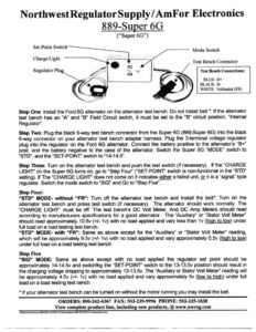
Northwest Regulator Supply/AmFor Electronics 889-Super 6G (“Super 6G”) Set-Poi itch et-Point Switc Mode Switch h Light Charge Lig Test Bench Connector Regulator Plug Test Bench Connections: BLUE: B+ BLACK: B- WHITE: Voltmeter (FR) Step One: Install the Ford 6G alternator on the alternator test bench. Do not install belt *. If the alternator test bench has an “A” and “B” Field Circuit switch, it must be set to the “B” circuit position, “Internal Regulator’. Step Two: Plug the black 6-way test bench connector from the Super 6G (889-Super 6G) into the black 6-way connector on your alternator test bench adapter harness. Plug the 3-terminal voltage regulator plug into the regulator on the Ford 6G alternator. Connect the battery positive to the alternators “B+” post, and the battery negative to the case of the alternator. Switch the Super 6G “MODE” switch to “STD”, and the “SET-POINT” switch to “14-14.5”. Step Three: Turn on the alternator test bench and push the test switch (if necessary). If the “CHARGE LIGHT” on the Super 6G turns on, go to “Step Four’ (“SET-POINT” switch is non-functional in the “STD” setting). If The “CHARGE LIGHT” does not come on it indicates either a failed unit, or it is a “signal” type regulator. Switch the mode switch to “SIG” and Go to “Step Five’. _Step Four: “STD” MODE- without “FR”: Turn off the alternator test bench and Install the belt*. Turn on the alternator test bench and press test switch (if necessary). The alternator should work normally. The “CHARGE LIGHT” must be off. The test bench’s DC Volt Meter, And DC Amp Meters should read according to manufacturers specifications for a good alternator. The: “Auxiliary” or “Stator Volt Meter” should read approximately 10.5v (+/- 1v) with no load applied and vary less than 1v (high to low) under full load on a load testing test bench. “STD” MODE- with “FR”: Same as above except for the “Auxiliary” or “Stator Volt Meter’ reading, which will be approximately 9.5v (+/- 1v) with no load applied and vary approximately 5.5v (high to low) under full load on a load testing test bench. Step Five “SIG” MODE: Same as above except with no load applied the regulator set point should be approximately 14-14.5v and switching the “SET-POINT” switch to the 13-13.5v position should result in the charging voltage dropping to approximately 13-13.5v. The “Auxiliary or Stator Volt Meter” reading will be approximately 4.5v (+/- 1v) with no load applied and vary approximately 5v (low to high) under full load on a load testing test bench. * If your alternator test bench can be tumed on without the motor running y you may install the belt. ORDERS: 800-242-6367 FAX: 503-239-9996 PHONE: 503-235-1038 View complete product line, including new products, @ www.nwreg.com \Pde
wrInventory889889-SUPER 6Ginstructions889 SUPER 6G-Instructions.doc