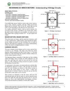
Technical Document MI-0707A Produced by the Electrical Rebuilder’s Association www.electricalrebuilders.org REVERSING DC WINCH MOTORS – Understanding H-Bridge Circuits Article Table of Contents: H-Bridge Circuits Winch Diagrams: Early-Style, 4 Solenoids, Three-Post Motor Early-Style, 4 Solenoids, Permanent-Magnet Motor Late-Style, 2 Solenoids, Three-Post Motor Late-Style, 2 Solenoids, Permanent-Magnet Motor Warn Winch Solenoid Packs Two-Post and Three-Post Motor Testing = NOOR WD Convertible tops, power windows, power seats, power mirrors, power locks, sunroofs, winches, and lifts. What do all these things have in common? They all use DC motors that can run CW or CCW depending on the direction the current flows. For smaller automotive motors, such as power mirrors, the reversing of the current is handled in the switch itself. Since the entire switch is replaced as an assembly, we rarely have to think about what is going on inside of it — we just replace the switch. BIGGER MOTORS, BIGGER SWITCHES When the motors are larger, and the amp draw increases, such as with a winch motor, small switches cannot handle the higher current. Relays are used to do the switching. Now, in order to diagnose and repair the equipment, you need an understanding of how the circuit is designed and how it works. H-BRIDGE CIRCUITS The most common circuit design used to reverse current flow is known as an H-Bridge. The name came from the circuit diagram, which resembles the letter H (see Figure 1). The load (motor) is on the horizontal line and the switches (relays) are on the vertical branches of the H. The important thing to remember is that there are four switches within the bridge. These switches are often referred to as; left high side, right high side, right low side and left low side (see Figure 1). The switches are always turned on in pairs to control the direction of current flow. To send power to the motor, you turn on the two switches that are diagonally opposed. In Figure 2 the left high side and the right low side switches are turned on. This allows current to flow, and the motor begins to turn. Figure 3 shows the opposite pair of switches turned on, and you can see that the current flow to the motor is now reversed. Most circuits are designed so that the motor will turn CW when the left high side and the right low side are turned on and turn CCW when the right high side and the left low side are turned on. This is not a hard-and-fast rule though, so always verify that the direction of rotation is correct after repairs. Motor Power (+ Left High Side I 7 Right High Side Left Low Side MOTOR Right Low Side Motor Ground (-) Figure 1 — H-bridge circuit layout High Side – ~% Power (+) Left High Side Right High Side Left Low Side MOTOR Right Low Side Low Side – Motor Ground (- Figure 2— Left High, Right Low turned on High Side – og Power (+) Left High Side Right High Side Left Low Side MOTOR Right Low Side Low Side – Motor Ground (- Figure 3 — Right High, Left Low turned on Created by Wes Grueninger for the Electrical Rebuilder’s Association – © 2007, Electrical Rebuilder’s Association — All rights reserved 1 No portion of this guide may be reproduced in any way, or stored in any electronic retrieval system without the prior written consent of the Electrical Rebuilder’s Association. Technical Document MI-0707A Produced by the Electrical Rebuilder’s Association www.electricalrebuilders.org GENERIC WINCH MOTOR DIAGRAM 1 e Four Early-Style SPST (single-pole, single-throw) Solenoids e Three-Post Motor with Field Coils This example is the setup that is most commonly used on heavy duty winches. It is used by most major winch manufacturers, including Warn and Ramsey. The four corners of the H-circuit are single-pole, single-throw solenoids. The solenoids may be tin-can style, as shown in Figure 4, or the later style phenolic housing solenoids as shown to the immediate right. The solenoid coils may be internally grounded, or they may have insulated coils. If the solenoid has one small stud, then the coil is internally grounded. If there are two small studs, then it is the insulated style. See the note in Figure 4 for information about completing the ground circuit for insulated-coil solenoids. Figure 5 shows the motor current flow highlighted when the winch control switch is in the CW position. In CW mode, the left high side and the right low side solenoid coils are energized, causing the solenoid contacts to close. Current now flows: 1. From the battery positive post, through the left high side solenoid to terminal C on the motor. 2. From terminal C, it flows through the motor’s field coils and exits through terminal B. 3. From terminal B, it flows through the right low side solenoid and back into the motor through terminal A. 4. It continues through the positive brushes and armature and finally through the negative brushes to ground. In CCW mode, the right high side and left low side solenoids are energized and the current flow is reversed through the field coils, changing their magnetic polarity. It is important to note that in either CW or CCW mode, the current applied to the armature does not change direction. The current flow through the armature is always from positive to negative. Early-Style Normal Position Coil Energized SPST Contacts Open Contacts Closed Note: Solenoid coils come in two styles. If the solenoid has only one small stud, then the coil is grounded inside the solenoid. If the solenoid has two small studs, then you must provide a ground connection to complete the circuit. In the example shown above, there are two small studs. This style is known as an insulated-coil solenoid. Figure 4 — Early-Style Solenoid Operation Q00000 LOW SIDE Figure 5 — Early-Style, 4 Solenoids, Three-Post Motor with Field Coils Created by Wes Grueninger for the Electrical Rebuilder’s Association – © 2007, Electrical Rebuilder’s Association — All rights reserved 2 No portion of this guide may be reproduced in any way, or stored in any electronic retrieval system without the prior written consent of the Electrical Rebuilder’s Association.