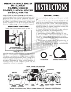
SPEEDWAY COMPACT STARTER INSTALLATION 910-66258, 910-66259 910-67400, 910-67430, 910-67433 910-67439, 910-67440 PLEASE READ OVER ALL INSTRUCTIONS BEFORE INSTALLING STARTER Install the Compact Starter similarly to the factory starter. Some applications require shims, spacers and/or minor fabrication. Check pinion to ring gear clearance at numerous positions on the ring gear. Gross variations indicate a bent or out of round flywheel; see figures “A” and “B” for acceptable tolerances. Starter and ring gear damage will occur if installed improperly. PINION TO RING GEAR CLEARANCE Check the starter pinion to ring gear clearance (see figure “A”). STARTER PINION TO RING GEAR CLEARANCE FIGURE “A” When the pinion is retracted (disengaged) the gap should be .100″ (plus or minus .040) between the pinion and the ring gear. If the pinion is too close to the ring gear (pinion to ring gear clearance) it will be necessary to install the two (2) shims (.062″) which are supplied with the starter. To accomplish this, it is necessary to disassemble the starter. Previous experience of assembling starters required. Familiarize yourself with the exploded view and refer to it as needed. DISASSEMBLY / ASSEMBLY A) Loosen the field wire retaining nut and disconnect the field wire. B) Loosen but do not remove the two bolts that hold the end cap to the gear reduction housing. Remove the field armature, brush, end cap and bolts as a unit. If this assembly does not come apart easily, it may be necessary to carefully work it back and forth to separate the armature shaft bearing from the gear reduction housing at the front of the motor. C) Remove the three bolts which hold the gear reduction housing to the starter nose and separate these pieces. NOTE: D, E, and F for pinion ring gear clearance only. D) Remove the pinion/sprag-clutch assembly from the nose. E) Place the round shim washer (provided) into the pocket and then replace the pinion/sprag clutch assembly in the pocket. F) Place the housing shaped shim (provided) between these components. G) Assemble the rest of the starter in the reverse order of disassembly. CAUTION!! Do not over tighten the two case bolts (1/4″x 5″) as this will distort the end cap and overload the bearing causing probable failure. ROUND SHIM HOUSING SHAPED SHIM TYPICAL STARTER EXPLODED VIEW SOLENGID i | / i f; J “END CAP | ARMATURE i seu fotos BSH + ARMATURE ARMATURE ASSEM END BEARING SHAFT BEARING aby * Optional: Use to increase starter pinion to ring gear clearance [NOT INCLUDED IN REBUILT STARTER) BACK LASH After pinion is engaged, there should be .010″ to .030″ back lash between the pinion and ring gear (see figure “B”). To check back lash, bend a 3/8″ wide strip of metal in a “U” shape and place it behind the pinion after it has been pulled out by hand. This will hold the pinion in mesh with the ring gear to check back lash. GENERAL MODIFICATIONS Although the Compact Starter has more oil pan clearance than most starters, it can still be a tight fit at the rear corner of the pan. First check to see if your model has an indexable nose. If it does, you can rotate the body to gain additional clearance. See “Disassembly/ Assembly” for rotating the nose. If more clearance is necessary, the gear drive casing can be relieved by grinding and the reduction gear retaining bolt boss shortened. Sometimes the pan can be creased or the corner cut off and a plate welded in. The quality and performance of the Compact Starter is worth the effort-to make some minor modifications to the pan or engine. CHEVROLET Some Chevrolet cylinder blocks only have the staggered starter mounting bolt pattern. To mount a Speedway Compact Starter on these blocks, accurately mount the starter to the existing bolt hole and, using the starter nose as a guide, move over two holes and spot the block with a 3/8′”drill. Remove the starter and drill the spotted hole 1- 1/2″ deep with a 5/16″ drill and tap 3/8″x 16. This problem PRE HTL LOWER STL FPGURE =C ELECTRICAL CONNECTION There are three working wire terminals om thee solenoid. Two threaded (2mm) studs and one male spade (push on) ; (See figure “S*) See Figure “D”). Il PUEH A C So) at _ | FRELAE E STANDARD (General Motors} Connect the battery cable to the unused upper stud and the starter » yOu ewlich lead to the spade connection casting bypass: wine bo the lower stud a 10 amp. dhode is placed in the wire to prevent ieedback voltage from reaching ihe starter (See figure “E”). r starter swiich IF a ed does not have the correct female PUSh=On connecior, uae the connector is most often found in 400 cubic inch small blocks. RING GEAR BACK LASH -010” TO .030” FIGURE B co Li HOUSING SHAPED SHIM NOTE: Can be corrected by installing the rectangular shim between starter nose and engine. RECTANGULAR SH resigior IM FONITION RESISTOR BYPASS if your vehiche mequires an ignilian eam Gormect the ELECTRICAL CONNECTION There are three working wire terminals on the solenoid. Two threaded (8mm) studs and one male spade (push on). See figure “C”. eupplied with the staster, STANDARD (General Motors) Connect the battery cable to the unused upper stud and the starter switch lead to the spade connection (See Figure “D”). If your starter switch lead does not have the correct female push-on connector, use the connector supplied with the starter. IGNITION RESISTOR BYPASS If your vehicle requires an ignition resistor bypass, you can connect the existing bypass wire to the lower stud IF a 10 amp diode is placed in the wire to prevent feedback voltage from reaching the starter (See Figure “E”). There are two methods of connecting the starter. Use the one that is appropriate for your application. Speedway Motors Inc., P.O. Box 81906 Lincoln, NE 68501 (402) 323-3200 www.speedwaymotors.com S5PEEDWAY’ a >» @ ©2006