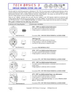
TECH BASICS 3 CHRYSLER CHARGING SYSTEMS 1961-1987 Chrysler made the switch from generators to alternators in 1961. The first system used a one field-terminal alternator with an external mechanical point-style voltage regulator and remained unchanged until 1970. In 1970, Chrysler changed to a two field-terminal alternator with an external solid-state electronic voltage regulator. This system was used until the mid 1980s when the voltage regulator was moved inside the engine control computer. There are two “oddball” variations that were used. The first “oddball” is the 1969 Imperial, which has an alternator and voltage regulator that fits only that one year and model. The second “oddball” was introduced in 1974 on cars that use a large case 100 amp alternator. A special Field and Load relay was installed to reduce engine load while the starter was cranking. This guide is divided into the following subsections: Alternator and Voltage Regulator Section name / description e 1961 – 1969 one field-terminal alternators g ONO p a * One spade-connector field-terminal on alternator. Y On y | ¢ Voltage regulator is mechanical (not solid state). Use section 1961 – 1969 ONE FIELD-TERMINAL ALTERNATORS 1969 Imperial * One spade-connector field-terminal on alternator. ¢ Voltage regulator is solid-state with three terminals. ¢ Used only in 1969 and only on Imperial models. Use section 1969 IMPERIAL ONLY 1970 – 1971 two field-terminal alternators ¢ Two spade-connector field-terminals on alternator. ¢ Voltage regulator is solid-state with two terminals. Use section 1970 – 1987 TWO FIELD-TERMINAL ALTERNATORS 1972 – 1987 two field-terminal alternators * Two spade-connector field-terminals on alternator (screw-on connectors in later years). Voltage regulator is solid-state with two terminals. Use section 1970 – 1987 TWO FIELD-TERMINAL ALTERNATORS 1974 -1987 two field-terminal large case alternators ¢ Two spade-connector field-terminals on alternator. ¢ Voltage regulator is solid-state with two terminals. ¢ Some vehicles use a Field and Load relay ( see section FIELD & LOAD RELAY – 1974 to 1976). Use section 1970 – 1987 TWO FIELD-TERMINAL ALTERNATORS 02/2003 Copyright © 2003 Wesley S. Grueninger – All Rights Reserved Page | TECH BASICS 3 CHRYSLER CHARGING SYSTEMS 1961-1987 1961 – 1969 ONE FIELD-TERMINAL ALTERNATORS ©0000 2 Battery Fusible Link Ammeter Fuse Ignition Switch Voltage Regulator o oomogOS Alternator t% How it works: With the engine running, current flows from the battery > through the fusible link ™ through the ammeter > through the fuse > through the ignition switch > to the voltage regulator IGN terminal. The voltage regulator controls alternator charging by varying the current it sends to the alternator FLD terminal. Dark Blue When the alternator is charging, current flows from the alternator B+ terminal > through the ammeter = through the fusible link > to the battery positive terminal. Figure I – 1961 to 1969 charging system How to test and repair Start by doing these tests in the order below: Remove the JGN connector from the voltage regulator. With the key on and the engine off, test for battery voltage at the wire that goes to the voltage regulator IGN terminal. If no voltage or low voltage is found, check the wiring, fuse, or fusible link and repair as needed. Reconnect the wire to the voltage regulator [GN terminal. The voltage regulator must be properly grounded. Inspect the screws and body area where it mounts and sand off any corrosion. Remove the FLD wire from the voltage regulator. With the key on and the engine off, test for battery voltage at the voltage regulator FLD terminal. If no voltage is found, the voltage regulator is bad and must be replaced. If the regulator is bad, read the section at the end of this guide titled ROTOR WARNING. Remove the belt from the alternator. Remove both the FLD and the IGN wires from the voltage regulator. Connect the two wires removed from the voltage regulator together. With the key on and the engine off, place the flat blade of a screwdriver against the rear bearing of the alternator. If the alternator field circuit is good, you will feel a magnetic pull on the screwdriver. Slowly turn the pulley while performing this test. If the magnetic pull goes on and off while turning the pulley, or if there is no magnetic pull, the alternator is bad and must be replaced. Test for battery voltage at the alternator B+ terminal. If low or no voltage, check the positive battery cable, the fusible link (some early cars do not have fusible links), and the ammeter. Many of the 1960’s cars use a direct-style ammeter. This style ammeter passes all the charging current through the meter. It’s common for these meters to go “open” and not allow any current flow. Reconnect all wires and perform the Charging System Test described at the end of this guide. 02/2003 Copyright © 2003 Wesley S. Grueninger – All Rights Reserved Page 2