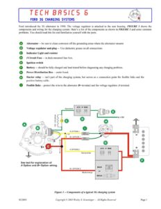
TECH BASICS 6 FORD 3G CHARGING SYSTEMS Ford introduced the 3G alternator in 1990. The voltage regulator is attached to the rear housing. FIGURE 1 shows the components and wiring for the charging system. Here’s a list of the components as shown in FIGURE I and some common problems. You should read this list and familiarize yourself with the parts. Alternator — be sure to clean corrosion off the grounding areas where the alternator mounts Voltage regulator and plug — Use dielectric grease on all connections. Indicator Light and resistor I Circuit Fuse — in dash-mounted fuse box. Ignition switch Battery — should be fully charged and load tested before diagnosing any charging problem. Power Distribution Box — under hood. Starter relay — isn’t part of the charging system, but serves as a connection point for fusible links and the positive battery cable. be Re Oe Ae ee ie De Be Fusible links — protect the wire to the alternator B+ terminal and the voltage regulator A terminal. Green/red F 100 – 510 ohms FUSIBLE LINK xx GA. FUSIBLE LINK xx GA. A OPTION 2 Yellow/white See text for explanation of A Option and B+ Option wiring. B+ OPTION 2 Black/orange Figure 1 — Components of a typical 3G charging system 02/2003 Copyright © 2003 Wesley S. Grueninger – All Rights Reserved Page 1 TECH BASICS 6 FORD 3G CHARGING SYSTEMS CHARGING SYSTEM – How it Works The charging system has four separate circuits. They are the J, §, A and B+ circuits. Each circuit, except the S, is protected by either a fuse or a fusible link. The following section will explain the function of each circuit. ¢ I CIRCUIT – (color code green with red stripe) The J circuit controls the indicator light and turns on the charging system. The voltage regulator turns on the indicator light by completing the ground path for the light bulb. When the voltage regulator senses current at the J terminal, it turns on the alternator and starts to charge. The / circuit is protected by a fuse located in the dash-mounted fuse box. ¢ § CIRCUIT – (color code white with black stripe) Once the alternator starts charging, its sends a signal to the S terminal of the voltage regulator. When the voltage regulator senses current at the § terminal, it opens the ground path at the J terminal which causes the indicator light to go out. The S circuit is not fused. ¢ A CIRCUIT – ( color code yellow with white stripe) The voltage regulator uses the A circuit to sense the battery state and adjust the charging system output as needed. The A circuit is also the source of field current inside the alternator. The A circuit can be protected in two different ways: 1. A fusible link wire that attaches to the starter relay (see Figure I – A option 1). 2. A fuse in the under-hood fuse box (see Figure I – A option 2) ¢ B+ CIRCUIT – (color code black with orange stripe) The B+ circuit is the path the alternator-produced current follows to power accessories and charge the battery. The B+ circuit can be protected in three different ways. 1. A fusible link wire that attaches to the starter relay (see Figure I – B+ option 1). 2. A maxi-fuse in the under-hood fuse box (see Figure I – B+ option 2) 3. A mega-fuse. Most mega-fuses are mounted on the outside of the power distribution box (see Figure I – B+ option 2). A few vehicles (Contour/Mystique and trucks with diesel engines) have the mega-fuse mounted on the engine. 02/2003 Copyright © 2003 Wesley S. Grueninger – All Rights Reserved Page 2 TECH BASICS 6 FORD 3G CHARGING SYSTEMS HOW TO TEST AND REPAIR START BY DOING A CHARGING SYSTEM TEST. Step 1. The battery must be fully charged and load tested. The engine must be off. Be sure the alternator belt is properly tensioned. Connect the negative lead of a voltmeter to the negative battery post and the positive voltmeter lead to the positive battery post. Write down this reading – it will be referred to as “base voltage”. Do both of the following tests: LOAD TEST: Start the engine. Turn the headlights on and the heater/ac motor to high. Increase engine speed to 2000 RPM. Check the voltage across the battery terminals. See chart for results. LOAD TEST VOLTAGE READINGS. RESULT: Voltage increases at least 0.5 volts over “base voltage” Voltage does not increase at least 0.5 volts over “base voltage” NO-LOAD TEST: Turn off the accessories, decrease engine speed to 1500 RPM and check the voltage across the battery terminals again. See chart for results. RESULT: NO-LOAD TEST VOLTAGE READINGS Voltage is less than 2.0 volts over “base voltage” Voltage is more than 2.0 volts over “base voltage” VY If both LOAD TEST and NO-LOAD TEST Pass and charge-light is out, the charging system is working correctly. Y IfLOAD TEST Fails, skip to Step 2. VY If NO-LOAD TEST Fails, the alternator is faulty. Repair and repeat Step 1. Steps 2 – 3 are performed with the engine off Step 2. Use a voltmeter or a test-light and check for power at the B+ output stud at the rear of the alternator. If power is present, skip to Step 3. If no power, check the fusible link or maxi-fuse or mega-fuse as shown in Figure I. Repair and retest. Step 3. Remove the voltage regulator plug from the alternator. Turn the key to the “run” position (engine off). Use a voltmeter or a test-light and check for power at both the J and the A terminals of the voltage regulator plug (not the alternator). If there is no power to the A terminal of the voltage regulator plug, check for a broken wire or a poor connection at the plug. Also check for a bad fusible link or a bad fuse as shown in Figure 1. Repair and retest. If the voltage regulator J terminal does not have power, the most likely cause is a bad fuse in the dash-mounted fuse box as shown in Figure 1. If the fuse is good, it’s time to start checking for unusual problems. Check for corroded connectors, corroded fuse box terminals, cut wires, loose plug at the instrument cluster or a bad ignition switch. What about the bulb? A bad bulb will not prevent power from flowing to the regulator plug J terminal, since the resistor offers an alternate path. The time to test the bulb is after restoring power to the regulator plug J terminal. Just ground the J terminal from the voltage regulator plug and the charge-light will come on if the bulb is good. Reconnect the plug to the voltage regulator. Make certain the key is still in the “run” position (engine off). If the charge-light comes on, go to Step 4. If the charge-light does not come on, the alternator is faulty. Replace the alternator and repeat Step 1. 02/2003 Copyright © 2003 Wesley S. Grueninger – All Rights Reserved Page 3