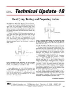
87-229-2 March 1994 Identifying, Testing and Preparing Rotors Identify Some Rotors by Physical Measurement Rotors can be hard to identify because many of them look very much alike. Certain of these look- alike rotors can be identified by measuring the pole pieces, because, even though the rotors may be visu- ally similar, their pole pieces are actually slightly dif- ferent sizes. Rotors for Delco CS144 alternators are a case in point. The rotor body (pole pieces and field coil) on 108-120-amp units is 54.5 mm thick, whereas the body for 124-, 140- and 145-amp units is 57 mm thick. (See Figure 1.) This small difference is not easy to see but can easily be measured. For more details on identifying these rotors, see Technical Update 11 (July, 1993). II 54.5 mm or 57 mm Figure 1. On Delco CS144 alternators, the rotor body for 108-120-amp units is 54.5 mm thick, whereas the rotor body for 124-, 140- and 145-amp units is 57 mm thick. Look-alike rotors for Ford IAR alternators can also be differentiated by measuring. In this case, the pole pieces on rotors for 40-65-amp units are 9 mm thick, but the pole pieces for 75-amp units are 10 mm thick, even though the rotor bodies are the same dimension. (See Figure 2.) 9mm or 10 mm Figure 2. On Ford [AR alternators, the pole pieces on rotors for 40-65-amp units are 9 mm thick, but the pole pieces for 75-amp units are 10 mm thick. This is the only difference between the two rotors. Identify Most Rotors by Electrical Measurement In many cases, however, look-alike rotors have the same physical dimensions. In these cases, you have to use electrical measurement in order to know which one you have. Do this by conducting an amp- draw test. This will tell you, in most cases, which style alternator the rotor was intended for. For example, a Delco 1ODN 12-volt alternator uses a rotor with an amp draw of 2.5 to 3.2 amps, whereas a Delco 10SI 12-volt alternator uses a rotor with an amp draw of 3.8 to 4.5 amps. These two rotors look alike but it’s important to know which one you have, because if you install a rotor intended for a 10SI into a 1ODN, the higher amperage draw will destroy the contacts in the vibrating-contact regulator. Conversely, if you install a [ODN rotor into a 10SI, it takes more rotor RPMs to turn on the alternator, and the output of the alternator is decreased. In the Delco 15 and 17SI series, if the rotor’s amp-draw reading is approximately 7 amps, you have a rotor for the 17SI 120-amp alternator. This alter- nator requires a regulator with a power transistor that is capable of handling this higher amp draw. Continued on page 2 WAIL Wetheritt associates, inc. + 1101 Enterprise Drive « Royersford, PA 19468 = 800-877-3340 Care is taken to ensure the accuracy of information presented here, but Wetherill Associates, Inc., assumes no responsibility for possible errors. Copyright © 1994 Wetherill Associates, Inc. 3606 In addition, Ford and Chrysler have some rotors that are hard to tell apart visually. One rotor is for their early vibrating-contact regula- tors and draws 2.8 to 3.2 amps. The other is for their later electronically regulated alternators and draws 3.8 to 4.2 amps. Ford stamped “4A” on the pole piece of the 4-amp rotors, but we don’t know if all rewinders do this. Finally, rotors for Ford IAR (internal regu- lated) alternators draw approximately 5 amps. Be Sure to Check Their Condition First However, before you do any kind of elec- trical testing on a rotor, we recommend that you check its overall condition. First inspect the windings to make sure they are not cut, burned, or loose on the spool. Next, check the connec- tions where the rotor coil attaches to the slip ring. Also check the area where the rotor-coil wires come around or through the pole pieces. You should also conduct a leakage-to-ground test (also known as grounding or shorting-to- ground) on all rotors. This test checks the quality of the insulation between the windings and pole pieces. With a hi-pot tester you can conduct this test using high enough voltage to find the rotors that are grounded. This test will also find problem rotors whose insulation is breaking down, which can save you time and trouble in the long run by alerting you to potential flying grounds. (A flying ground can occur during high rotor RPM when the rotor coil becomes grounded to the pole piece.) CAUTION: Because of the high voltage, hi-pot testers are dangerous. Read and follow the manufacturer’s instructions completely. As an aside, note that a flying short can be harder to find than a flying ground. In a short, the windings are touching each other and drawing higher amperage, but are not going to ground. To help locate a flying short you should do an amp- draw test while the rotor is spinning. High or Low Output? Knowing the amp draw of a rotor, however, still doesn’t tell you if the rotor is for a high- or low-output alternator. Two rotors can have the same amp draw, but produce different outputs, even with the same stator. To determine if the rotor is for a high- or low- output alternator, look at the spool. If it is full, the rotor is for a high-output alternator, since more turns of wire mean higher magnetic strength. However, keep in mind that this is not entirely foolproof, since some manufacturers may start with a larger diameter bobbin. The most accurate method for determining if the rotor is for a high- or low-output alternator is to measure the magnetic strength of the rotor using a Gauss meter. For accurate results, you must be able to measure the magnetic strength in the same exact spot for each rotor being tested, so you will need a fixture and gauge that will allow this. You will also need a power supply that remains constant throughout testing. Tips for Completing Preparation There are several more steps to completing preparation of a rotor. First, slip rings must be polished with 400-600 grit paper or a polishing stone to prevent the brushes from arcing. Spike voltages from brushes that are arcing can destroy the voltage regulator, computer and other elec- tronic components. Keep in mind that the run-out of the slip ring should not exceed .002.” Also, when you are turning down a slip ring, do not remove more material than is absolutely necessary. A thin slip ring will distort more easily than a thicker one. In alternators that use a needle or roller bearing, you should also check the inner bearing race at the SRE end. In most cases this is the shaft of the rotor. In addition, chase the threads to clean and straighten them. This allows for more accurate torquing of the fan nut. Caution: There has been a change in the thread size and torque on Ford 3G alternators. Early style units are .668 x 20 U.S. with approximately 70 Ibs torque. Later style are M16 x 1.5 metric with approximately 120 lbs torque. Also remember that sanding the outside of a rotor or the inside of a stator increases the air gap between the rotor and stator. With this increased air gap, the alternator requires more rotor RPMs before it cuts in (starts charging). If the gap is too large, the alternator may not cut in at all. This is especially true of one-wire (self-exciting) alter- nators, which rely on the residual magnetism of the rotor to start the system charging. Finally, note that there is a direct relationship between the number of fingers on the pole pieces of a rotor and the number of segments in a stator lamination. There are three times as many seg- ments in a stator as there are fingers in a rotor. So a rotor with eight fingers (four on each side) has a stator with 24 segments. A rotor with 12 fin- gers (six on each side) has a stator with 36 seg- ments, and so forth.