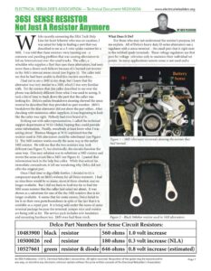
www.electricalrebuilders.org hile recently answering the ERA Tech Help Line for Scott Scharrer who was on vacation, I was asked for help in finding a part that was described to me as a 3-wire spider resistor for a 36SI. I was told that these resistors were burning out – a common and puzzling problem that was causing alternators to fail on International over-the-road trucks. The caller, a rebuilder who supplies a fleet that uses these alternators, had seen more than a dozen such failures because of a burned out resistor in the 36SI’s internal sense circuit (see Figure 1). The caller told me that he had been unable to find this resistor anywhere. Thad yet to see a 36SI in my shop, but I knew that the alternator was very similar to a 34SI, which I was very familiar with. Yet the resistor that this caller described to me over the phone was definitely different from what I was used to seeing. It took a lot of time to track down the part that the caller was looking for. Delco’s online breakdown drawing showed the sense resistor he described but they provided no part number. J&N’s breakdown for that alternator did not show the part either. After checking with numerous other suppliers, it was beginning to look like the caller was right. Nobody had even heard of it. Striking out with sales representatives, I called the technical support department at WAI-Global, hoping they could provide some information. Finally, somebody at least knew what I was asking about. Thomas Morgan at WAI explained that the resistor used in 34Si alternators could be substituted (see Figure 2). The 36SI resistor works exactly the same way as the earlier 34S] resistor. He told me that the two resistors may look different (see Figure 3), but electrically, the circuits function the same way. One easy solution was to substitute a 34SI resistor and rewire the sense circuit like a 34SI (see Figure 4). I passed that information back to the help line caller. While that solved his immediate conundrum, it left me wondering why Delco did not offer the original part. Once I had time to dig a little further, I decided to try a component search on J&N’s website for all Delco resistors. I had no idea there would be so many, most of them obsolete and no longer available. But I did not have to look too far to find the 36SI sense resistor that the caller had asked me about. It was shown as a substitute for one of the the 34SI resistors that is no longer available. It seems that for some reason, Delco failed to list it on their own parts breakdown in spite of the fact that it is available as a repair part. It is being sold under the name of sense terminal package because the terminal, jumper wire and resistor are being sold as kit. The service pack includes new insulators and mounting hardware too. J&N even had them stock. BY KEN PLOURDE What Does It Do? For those who may not understand the resistor’s purpose, let me explain. All of Delco’s heavy duty SI series alternators use a regulator with a sense terminal – the small post that is right next to the webbed spade terminals. These voltage regulators use that post for voltage reference only to maintain their individual set points. In many applications remote sense is not used and a Figure 1 – 36SI Alternator terminals showing the resistor that had burned. Figure 2 – Black 560ohm resistor used in 34SI alternators. Delco Part Numbers for Sense Circuit Resistors: 10483900 10500026 10527661 black 560 ohms | 1.0 volt increase 180 ohms | 0.3 volt increase (NLA) resistor & diode | 646 ohms | 0.8 volt increase (estimated) An ERA Publication. ©2015, Electrical Rebuilder’s Association. All rights reserved. No portion of the guide may be reproduced in Page 1 any way, or stored in any electronic retrieval system without the prior written consent of the Electrical Rebuilder’s Association. www.electricalrebuilders.org simple jumper wire or strap connects the sense terminal to the positive heat sink (see Figure 5). That will work well so long as voltage loss due to resistance in the charge circuit is kept to a minimum. However, if the batteries are far away from the alternator, a drop in voltage between the two is inevitable and that loss can easily result in undercharged batteries. In those types of applications, the vehicle manufacturer may choose to use remote sense through a dedicated sense wire from the batteries to an external sense terminal on the alternator. Inside the alternator, it is connected directly to the sense terminal on the regulator. Remote sense is an option that may be found on any 33SI, 34S], 35S] or 36S] alternator. These regulators require a minimal amount of current to sense voltage. Therefore a small gauge wire may be used in the harness to supply voltage to the sense terminal. But in the event that the sense wire breaks, becomes disconnected or is accidentally left unconnected at either end, the regulator will loose sense voltage and the alternator will stop charging. These regulators cannot function without voltage on the sense terminal. Figure 3 – New 36SI sense terminal package above the 34SI resistor. Figure 4 – Red 180 ohm 34SI resistor installed in alternator. For reliability’s sake, a back up reference source is required when using remote sense. A direct connection to the positive rectifier will not work. The rectifier is always the highest point of voltage in any functioning charging system so a direct connection there would over-ride the lower sense voltage. Therefore Delco used a resistor between the regulator and the rectifier in any 34SI alternator that came with remote sense. That resistor is only there as a back up in the event that the primary source of sense voltage — the remote sense wire in the harness — becomes disconnected, broken or the alternator is being installed on an application that does not have a sense wire in the harness. When Delco first introduced the 34SI, they offered two sense resistors (see Figure 6). One was 180 ohms and the other was 560 ohms. They were color coded to make them easy to differentiate without having to measure resistance. The 180 ohm resistor was red and it created a backup increase of 0.3 volts above the regulator’s set point. The 560 ohm resistor was black and it created a 1.0 volt increase. Remember – this resistor should not affect voltage unless the remote sense circuit fails or no sense wire is attached. Later, when the 36SI was introduced, Delco built the resistor into a sense terminal service package. But there’s a catch. The new part is more than a simple resistor. I became curious when I noticed something on J&N’s website in their description of the part. They describe it as a sense terminal kit – which includes “resistor, diode and hardware”. I wondered if the word “diode” was a typographical error. More curious, I ordered one and tested it with my diode tester. No doubt, sure enough, there was a diode under the heat shrink covering. But was there a resistor in there too? All diodes drop voltage 0.7 volts. Interestingly that is about half way between the 0.3 and 1.0 volt drops of those 34SI resistors. I measured resistance of the new part and found it to be 646 ohms. How much of that is the diode? There was only one way to find out. I carefully removed the heat shrink. There I found a diode and a resistor in series (see Figure 7). The resistor measured 5.3 Figure 5 – B+ strap can be used only when voltage drop to batteries is minimal. An ERA Publication. ©2015, Electrical Rebuilder’s Association. All rights reserved. No portion of the guide may be reproduced in Page 2 any way, or stored in any electronic retrieval system without the prior written consent of the Electrical Rebuilder’s Association.