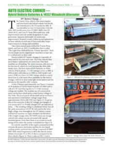
www.electricalrebuilders.org HV Battery Change…! he Toyota Prius, which is the most popular and most built/sold hybrid vehicle worldwide, was introduced in the US market in 2001. It was identified as Gen-I (Generation-I) for the 2001-2003 model years, Gen-II (2004-2009), Gen-III (2010-2015), and Gen-IV from 2016 until now, with improvements and sub-model designation in each generation. Japanese philosophy of continuous improvement (Kaizen) is truly evident in each generation Sammys Au Blecire Serve, In of these vehicles as each one of them embodies major improvements in design and reliability. I have been trained and certified for Toyota Prius repair, and have an ASE L3 certification that is called “The Light Duty Hybrid/Electric Vehicle Specialist”. Each Toyota dealer service department must have at least one L3 certified tech on their staff. Toyota hybrid HV battery changes is a specialty of mine and we do a few each year. The Prius vehicles that need battery replacement are some Gen-] but their numbers are dwindling. The most common calls now are for the Gen-II, which are built between the 2004-2009 model years. We have replaced HV batteries on Prius vehicles (Prii in plural…!) with mileages as low as 96K (a 2006 model) and miles up to 290K (a 2008 model) and even a 350K on a Gen-I of 2001 vintage which is a rarity. Since Gen-II is the most often candidate for the battery change, I will try to shed some light on its battery and the process in this month’s AEC column. A Gen-II battery pack assembly (see Figure 1) consists of 28 modules of Nickel Metal Hydride (Ni-MH) with 6 cells of 1.2V each that equates to 7.2 Volts nominal voltage per module. The modules are all connected in series via bus bars which gives a total battery voltage of 202 Volts. This is of course off the shelf and at rest but in real operation a total battery voltage ranges from approximately 220 to 240 VDC (see Figure 2). To get an idea of the enormity of this DC voltage, just imagine if you connected 17 to 19 fully charged 12V car batteries in series…! The resulting voltage is absolutely lethal, thus all the safety precautions MUST BE followed to the letter. High voltage wires throughout the HV battery system and hybrid transaxle are triple shielded and identified with a bright orange color. DO NOT touch any orange colored wire unless you are protected with special insulated gloves. Even then, there is no reason to touch orange wires unless the system is disabled (see Figure 3). An inverter assembly in the engine compartment that contains the power electronics and has its own liquid cooling system can boost that voltage to upward of 500V PDC with varied frequencies to drive the electric motor (Motor-Generator #2 or MG-2) that is connected to the drive wheels (Figure-4). There is also an MG-1 that is Figure 3 – Orange Wires Mean DO NOT TOUCH…! Sammy’s Auto Electric Service, Inc An ERA Publication. ©2020, Electrical Rebuilder’s Association. All rights reserved. No portion of the guide may be reproduced in Page 1 any way, or stored in any electronic retrieval system without the prior written consent of the Electrical Rebuilder’s Association. ELECTRICAL REBUILDER’S ASSOCIATION — Auto Electric Corner 2020_11 www.electricalrebuilders.org AUTO ELECTRIC CORNER smaller that cranks the engine for starting, and depending on the modes of operation, it can be a generator to charge the HV battery or a motor to assist MG-2 to drive the wheels. A very clever device that is a mechanical engineering marvel called the Power Split Device combines and manages the power of the ICE (the Internal Combustion Engine), MG-1, and MG-2, depending on the driving mode and the HV battery’s state of charge. Both MG’s can help drive the wheels or produce electricity, the ICE can either run or be shut down, or a combination of any of the above simultaneously and seamlessly without any input from the driver. The hybrid control system orchestrates the entire operation. Another power circuit in the inverter changes the high voltage into 14V, and serves like an alternator to charge the small 12V AGM battery that is also in the trunk. When you turn the ignition ON, all this battery does is wake up all the related modules and activate the battery contactor relays. It is not used for cranking. Before closing the relays and applying the HV into the system, it also checks for any HV leakage in the wiring, inverter, or in the hybrid transaxle modules that contain both motor-generators. If all is okay, it then introduces the HV into the system. It does it all in less than 200mS. All you hear is a faint double click, then the “Ready” light comes on the instrument cluster. You can start driving the vehicle as soon as the “Ready” light is on whether the ICE has started or not (see Figure 5). Sammy’s Auto Electric Service, ine © Figure 4 – Inverter Assembly in Engine Compartment i ia wc /50 3 NEe hon / aN an Sammy’s AutoElectric Service. inc Figure 5 – “Ready” Light Means All System Go! Each of the two modules that are called Battery Blocks are also wired into the HV Battery Control Module located inside the battery box. A long list of parameters of each block like the Voltage, State of Charge (SOC), as well as battery temperature are continuously monitored and measured by the HV Battery Module and are easily accessed via the scan tool (see Figure 6). It is important to know that the Ni-MH battery open cell voltage is not an indication of its state of charge. This is unlike the flooded cell lead-acid batteries that the open cell voltage of 12.6V indicates a fully charged battery. There are other factors involved but the HV Battery Module looks for variations in each block and through a special algorithm, calculates it and shows it as “Delta SOC” that can be seen by the scan tool. The system is designed to maintain each block at 45 to 55% state-of-charge. Seeing a 50% SOC is a good sign. At the same time, we are looking for the least amount of variation. The closer the variations in Delta SOC is to zero, the better the battery is. In new batteries after the installation this figure is always near 0% (see Figure 7). Bluish corrosion and salt build-up around each module’s post is always a sign of a deteriorated module and necessity for HV battery replacement (see Figure 8). Max Battery Block No 14 Battery Block Vol -V01 16.38 16.37 16.36 16.36 16.39 16.38 16.38 16.36 16.41 16.39 16.37 16.34 16.38 <<<