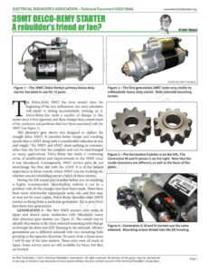
ELECTRICAL REBUILDER’S ASSOCIATION—Technical Document $S201506A www.electricalrebuilders.org 39MT DELCO-REMY STARTER Figure 1—The 39M, Delco-Remy’s primary heavy duty starter, has been in use for 15 years. he Delco-Remy 39MT has been around since the beginning of the new millennium, but some rebuilders still admit to feeling uncomfortable working on it. Delco-Remy has made a number of changes to this starter since it first appeared, and these changes have caused much of the confusion and problems that have been associated with the 39MT (see Figure 1). This planetary gear starter was designed to replace the straight drive 42MT. It provides better torque and cranking speeds than a 42MT along with a considerable reduction in size and weight. The 39MT and 42MT share nothing in common, other than the fact that the complete unit can be interchanged on many applications. Delco-Remy has made a continuing series of modifications and improvements to the 39MT since it was introduced. Consequently, 39MT service parts do not interchange like they did with the 42MT. It is of the utmost importance to know exactly which 39MT you are working on, whether you are rebuilding one or a batch of these starters. Having the OE starter part number before you do anything is highly recommended. Identification without it can be a problem with all the changes that have been made. There have been many aftermarket replacement units, too, and they may or may not be exact copies. Delco-Remy identifies their 39MT starters as being from a particular generation. Up to now there have been four generations. GENERATION I—The first 39MT starters were made in Japan and shared many similarities with Mitsubishi heavy duty planetary gear starters (see Figure 2). The easiest way to identify this starter is the three solenoid mounting bolts that go in through the drive end (DE) housing to the solenoid. All later generations use a different solenoid with two mounting bolts pointing in the opposite direction. No parts from a Generation I will fit any of the later starters. These units were all made in Japan. Some service parts are still available for them, but they are limited. BY BOB THOMAS PHOTO BY KEN PLOURDE Figure 2—The first generation 39MT looks very similar to a Mitsubishi heavy duty starter. Note solenoid mounting screws. Figure 3—The Generation II pinion is on the left,. The Generation III and IV pinion is on the right. Note that the inside diameters are different, as well as the faces of the gears. Figure 4—Generation II, Ill and IV starters use the same solenoid. Mounting screws thread into the DE housing. An ERA Publication. ©2015, Electrical Rebuilder’s Association. All rights reserved. No portion of the guide may be reproduced Page 1 in any way, or stored in any electronic retrieval system without the prior written consent of the Electrical Rebuilder’s Association. ELECTRICAL REBUILDER’S ASSOCIATION—Technical Document $S201506A www.electricalrebuilders.org GENERATION II—There was a complete redesign of the 39MT when production was moved to Korea for 2003. All 39MT starters after that move look very similar. Generation II starters can be identified by the flat face of the pinion gear on the left in the photo (see Figure 3). The pinion on the right was used only in Generation III and IV starters. If you are rebuilding a 39MT Generation II, you cannot use parts from the DE housing assembly of any other generation. The housing, pinion, pinion hardware, drive clutch and shaft are all different from later versions. The drive clutch shaft is 18mm in diameter. The solenoid for all Generation IJ, III and IV starters is the same and mounts differently as described earlier (see Figure 4). GENERATION III AND IV—Production was later moved to Mexico, and significant modifications were made to the Korean 39MT, which included a larger diameter drive clutch shaft. Most of the DE housing assembly was changed. These starters can be differentiated from their Generation II counterparts by the visibly different pinion gear as described above. The pinion hardware, clutch, shaft and DE housings are all different from Generation II. However, they may appear similar enough to get them mixed up or confused. An over crank protection (OCP) thermal switch similar to that used with the 42MT was originally added as an option, but it is now being included on all new 39MT starters (see Figure 5). Note that the self-resetting OCP switch is located on the brush holder right above a ground brush (see Figure 6). Perhaps the most popular feature to be added to the 39MT since its inception was the addition of rotatable DE housings (see Figure 7). This allows dealers and installers to achieve wider coverage with fewer part numbers. It also makes it possible to replace almost any aging 42MT with a 39MT. Soft Engagement Solenoid All versions of the 39MT incorporate a soft engagement feature that was designed to eliminate flywheel milling. The 39MT solenoid accomplishes this in a way that is different from past starters. The pull-in coil of this solenoid in 12 volt applications is wound with 10 gauge wire that requires about 230 amps. The hold-in coil draws an additional 40 amps. Combined, this solenoid needs 270 amps to work properly. The amperage draw of this solenoid during free-run bench testing, initially caused much concern in the rebuilding community. Current flows the same as it does in most other starter solenoids. All of the pull-in coil’s amperage flows through the starter’s motor as it travels to ground. This high current causes the 39MT’s motor to turn slowly, but with a significant amount of force, until the pinion is fully engaged into the ring gear. At that point the solenoid’s contacts close, the pull-in coil’s ground is lost, and the hold-in coil keeps the solenoid contacts and drive pinion in place during cranking. The ability to rotate a pinion at a controlled speed while it is pressed tightly against a ring gear, is what makes the 39MT’s soft engagement different. Extended cranking can easily overheat this solenoid, because it consumes over 3,000 watts during pull-in and 400 watts during cranking. Figure 5—The plug on the CE Housing is for the OCP thermal switch. THERMAL BREAKER Figure 6—The OCP thermal breaker is mounted on the brush holder, just above a ground brush. Once an option, it is now standard on all 39MT starters. PHOTO BY KEN PLOURDE Figure 7—The rotatable DE housing was introduced more recently and can be purchased as a component part to retrofit any Generation Ill or IV starter. An ERA Publication. ©2015, Electrical Rebuilder’s Association. All rights reserved. No portion of the guide may be reproduced Page 2 in any way, or stored in any electronic retrieval system without the prior written consent of the Electrical Rebuilder’s Association.