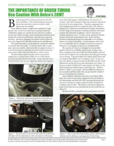
www.electricalrebuilders.org rush timing refers to the precise location of a DC motor’s brushes. A DC motor being any electrical device that uses direct current to rotate a shaft. Starters are one example. Every different starter is engineered to perform a single specific task. Its job is to rotate one or a group of internal combustion engines at a speeds that are sufficient to achieve success and reliable starting. Each manufacturer positions their brushes for maximum performance and efficiency to get that job done. Moving or changing any motor’s brush position by even a few degrees will affect that performance and efficiency. All magnetized objects possess polarity, commonly referred to as north and south poles. In close proximity, like or same poles repel one another, while poles that are opposite attract. It is the electromagnetic repelling and attracting forces between an armature and its field poles that drive a starter motor. The electrically magnetized pole shoes or permanent magnets in a cranking motor’s field case are nearly always permanently attached and immovable. As the armature turns inside that field case, its own magnetism distorts the magnetic a i Se Figure 1 – This Denso starter has protrusions on the field case, here fitting tightly into the drive end housing’s indentation. Figure 2 – The protrusion on the brush side of the Denso field case will align with the indentation on the commutator end housing. BY BOB THOMAS lines of the field magnets, shifting them in the direction of rotation. That shift is dependent upon the armature’s speed and the level of its own magnet force. Therefore, amperage draw and cranking speed must be considered when a DC starter is engineered, at which time optimal brush timing is determined. It is the design of an armature’s winding combined with brush position that ultimately establishes a starter’s direction of rotation and power curve. For that reason, alteration of brush position will result in performance loss. Brush timing is therefore predetermined and non-adjustable in all cranking motors, or at least it should be. In most instances, there is no way to accidentally alter or change it, even if you wanted to. However, it can happen in some cases, unintentionally. The majority of starters are designed to be assembled quickly without the possibility of getting the timing wrong. Many cranking motors have field cases, brush holders and end frames that fit together like puzzle pieces, basically guaranteeing correct timing. A good example is the Italian-made Denso that was used on some BMW cars (see Figures 1 & 2). As you can see in the photos, it has protrusions on the field case that match indentations on the drive end and commutator end frames. In the case of most of Delco’s MT series starters (see Figure 3), the brush holders are riveted in place to the field case – which is about as “fixed” as you can get. But the 28MT (see Figure 4) is one exception and that starter that can get you into trouble if you are not paying close attention. Delco utilized a small pin in the drive end of their 23MT field case to both insure proper alignment of the thru bolts to the intermediate and drive end (DE) housing and prevent the case from twisting out of place under the forces required for cranking a diesel engine. The field case also has an alignment mark on the field case near the field lead on the brush side (see Figure 5). The brush holder is attached to the commutator end (CE) y Figure 3 – Delco riveted the brush holders of their 10MT starters directly onto the field case, insuring perfect brush timing. An ERA Publication. ©2017, Electrical Rebuilder’s Association. All rights reserved. No portion of the guide may be reproduced in Page 1 any way, or stored in any electronic retrieval system without the prior written consent of the Electrical Rebuilder’s Association. www.electricalrebuilders.org housing. The CE housing has a line cast on it at the open end (see Figure 6) which must be aligned with the mark on the field case as shown. This insures perfect brush timing. Together with the pin, they insure the alignment of the thru bolts. Rebuilding an original Delco 28MT rarely causes problems so long as you line up the marks. However, when rebuilding an aftermarket replacement, all bets are off the table. Some units have pins while many do not. Some have alignment marks at different locations (see Figure 7) while others have no marks at all (see Figure 8). In that case, the thru bolts provide the only clue to get it right. But attempting to achieve perfect brush timing using just the thru bolts will only get you close. Whenever inspecting or dissembling a 28MT, it would be prudent to look for the alignment marks before you take it apart. Figure 4 – Some aftermarket 28MT starters present a unique In their absence, it might be wise to create some markings of challenge whether inspecting, repairing or rebuilding them. your own, assuming that nobody had it apart before and that it was perfect when it left a factory where perfect brush timing was not considered important. Incidentally, the majority of aftermarket 28MT starters that I inspected while working on this article had no timing marks or alignment pins. Special thanks to Art Glass for suggesting this pertinent topic. Figure 5 – Original Delco 28MT starters have locator marks on their field cases to achieve perfect brush timing. Figure 7 – Some aftermarket 28MT starters employ similar or identical timing marks. Figure 6 – A raised line cast on the open end of the commutator end housing must be aligned with the case’s mark. Figure 8 – Many other 28MT replacement starters have no timing marks at all. An ERA Publication. ©2017, Electrical Rebuilder’s Association. All rights reserved. No portion of the guide may be reproduced in Page 2 any way, or stored in any electronic retrieval system without the prior written consent of the Electrical Rebuilder’s Association.