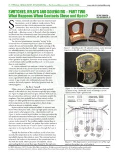
ELECTRICAL REBUILDER’S ASSOCIATION — Technical Document $S201709A www.electricalrebuilders.org SWITCHES, RELAYS AND SOLENOIDS — PART TWO BY BOB THOMAS & WES GRUENINGER, SR witches, solenoids and relays have one important part in common—a set of make-or-break contacts. These contacts are the critical component that controls current flow. They must be able to repeatedly establish and break a loaded electrical connection. That sounds like a simple task … allowing current to flow only when the contacts are closed and then immediately cease that current flow when the contacts open. But unfortunately, life underneath a solenoid cap is not that simple. The electrical phenomenon known as “arcing” is the unwanted flow of current which occurs prior to complete contact closure and immediately following the opening of the contacts. Anyone who has ever closely examined a set of worn out solenoid contacts, has seen what repeated arcing can do over time (see Figure 1). This type of wear is to be expected under normal use after many hundreds of on-off cycles. Each arc event transfers some material from one contact to the other—positive to negative. However, severe arcing can destroy a set of contacts rather quickly (see Figure 2)—or even cause them to weld together! In a starter solenoid, one stationary contact is typically connected directly to the positive side of the battery, while the other contact is connected to a very low resistance path to ground through an at-rest motor. In the case of a diesel engine starter, that ground path can carry a thousand amperes or more. A good battery bank can easily supply that kind of current. A gap of only a few millimeters between the open contacts, electrically separates the battery positive from the battery negative. An Arc is Formed While a new set of solenoid contacts may look perfectly smooth to the naked eye, they are microscopically quite rough (see Figure 3). High spots and low spots abound. With each use, the contact surfaces will wear, which will inevitably amplify the roughness. You have probably noticed that contact surface designs can differ greatly between manufacturers. Some have embossed patterns on their mating surfaces. Each design reflects an attempt to minimize arcing. If you could see inside a solenoid while it is activated and record what takes place with a close-up high-speed camera, you would observe what appears to be a catastrophic event! (see Figure 4) As the contacts begin to close, one tiny spot makes the first point of connection between the two surfaces. In technical terms, that point is known as a constriction, and all available current rushes toward it. The resulting sudden intense flow of electrons creates an extremely hot spot on the contact surface at the constriction. In the case of a diesel starter’s solenoid, this is equivalent to forcing hundreds of amperes through the head of a pin. Though the duration of this condition is only a few nano- seconds, the temperature at the surface of the constriction may reach 8,000 degrees Fahrenheit or more. This extreme heat not only melts the surface of the contacts at the constriction, but it also boils the metal, which can cause it to explode. The air surrounding the hot spot is then super-heated by the explosion Figure 1 – Used Denso 2.5 kW solenoid contacts, motor terminal (negative) on the left and battery (positive) on the right. Figure 2 – This 32 volt 40MT starter solenoid was destroyed by severe arcing. Notice that nearly all damage is on the battery contact (left) – positive side. Areasinactual [aE metallic contact Heke Surface film Inclusions in Other load contact metal bearing areas Figure 3 – This diagram shows a microscopic view of the high spots on the surfaces of a set of contacts. An ERA Publication. ©2017, Electrical Rebuilder’s Association. All rights reserved. No portion of the guide may be reproduced in Page 1 any way, or stored in any electronic retrieval system without the prior written consent of the Electrical Rebuilder’s Association. ELECTRICAL REBUILDER’S ASSOCIATION — Technical Document $S201709A www.electricalrebuilders.org SWITCHES, RELAYS AND SOLENOIDS – PART TWO oe = WOT FPL A ot =~ — a Figure 4 – These are making arcs between the center moving contact and both stationary contacts on a 1.2kW Denso starter during free spin testing. and is ionized when its electrons are stripped away. At this point, the ionized air (or plasma) itself begins to conduct current. Around the constriction and in the proximity of the explosion, an electrical arc is formed. That arc, conducted by ionized air, will exist until the next high spot forms another constriction. Then, the previously explained chain of events repeats itself, over and over. As each new arc is established, the previous arc is extinguished. Each arc transfers some contact material. Arcing cascades across the surfaces of the contacts, until the contacts are Two contacts As they conducting plasma, which was created when the contacts first touched, was made of ionized air. Now, the gap between the breaking contacts is filled with ionized liquid metal, causing an arc of a grander scale to be formed! Since the contacts are now opening, this arc (a breaking-arc) cannot be extinguished in the same way as the arc made when the contacts were closing (a making-arc.) The making-arc was terminated when current flowing through it was ultimately given a path of lower resistance to take (when the contact surfaces came tightly together). The breaking-arc will be sustained as long as there is sufficient energy to supply it—and as long as the arc exists, it will continue to transfer metal. The making-arcs and breaking-arcs are different in several ways. Making-arcs are numerous and brief, compared to the extended single breaking-arc (or occasional multiple break- ing-arcs.) A breaking-arc is much more violent, because it is made up of metallic ions, unlike the making-arc plasma, which is composed of ionized air. In addition, a breaking-arc has no definite ending. But the making-arc does end, when the contacts finally close completely—detouring the current to a path of lower resistance—essentially bypassing the plasma. The breaking-arc can be extinguished only by opening the circuit at another point (not very practical) or by exceeding the current’s impedance with more distance between the contacts. As they Which then Arcing .. and the finally forced tightly together— t L ; – anc latteri a Ited at rest separate, begin to bursts, persists until circuit splatteting any remaiming mene carrying contact area separate a initiating the circuit is breaking metal upon impact. This results in the | current decreases molten arcing cleared … process is loss of even more contact material eg isheas By aidge completed —N to the drawn out (the copper dust you often find inside melting point a used solenoid.) Once the contacts close completely, the last arc will be extinguished as the current flow is dispersed across the contact surfaces. The extreme temperatures that caused the arcing, begin to dissipate. As the molten metal cools, the contacts actually become fused together in a weak bond while the engine is being cranked. That bond is a “soft weld”, which can be broken by the solenoid’s release spring. The Grand Finale When the solenoid is de-energized, the release spring starts to break the contacts apart, with full-load current still flowing. As the contacts begin to move apart, the area of their touching surfaces decreases … until all flowing current is funneled into the last small area to break. The metal at that point becomes super-heated again and begins to melt. As the contacts move farther apart, a bridge of the molten metal forms between them and is stretched across the gap. With full-load current still flowing through it, the liquid metal bridge is stretched thinner, until it explodes into a shower of metallic ions (see Figures 5 and 6). As you recall, the Figure 5 – This sequence of diagrams shows how a breaking arc is formed as a set of contacts open. Figure 6 – This is an actual breaking arc on the battery side contacts of the same Denso starter during a free spin test. An ERA Publication. ©2017, Electrical Rebuilder’s Association. All rights reserved. No portion of the guide may be reproduced in Page 2 any way, or stored in any electronic retrieval system without the prior written consent of the Electrical Rebuilder’s Association.