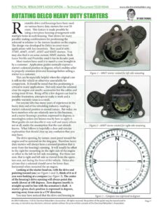
ELECTRICAL REBUILDER’S ASSOCIATION — Technical Document $S201904A www.electricalrebuilders.org ROTATING DELCO HEAVY DUTY STARTERS otatable drive end housings have been used on various heavy duty starters for over 50 years. This feature is made possible by using a two piece housing arrangement with multiple holes in each housing. That allows for many possible mating combinations for positioning the solenoid in relation to the starters location on the engine. The design was developed by Delco to cover more applications with less inventory. They used it with 37MT, 40MT, 41MT, 42MT and 50MT starters. You may also find it on some current 39MT starters. Both Leece Neville and Prestolite used it too in decades past. Most readers have used it to match a core brought in by a customer. Application guides normally express a starter’s solenoid position in degrees, which enables seller to properly orientate drive end housings before selling a starter to a customer. This can be especially helpful when the original core is still on the vehicle or otherwise unavailable for comparison. It should be noted that this positioning is critical in many applications. Not only must the solenoid clear the engine and nearby accessories but the cables and wiring must fit too. Being off by a few degrees can lead to installer frustration, attempts to make it work anda possible warranty issue as a result. For anyone who has many years of experience in the heavy duty end of the rebuilding industry, reading a starter’s solenoid position is second nature. But today, we have members who are relatively new to this business, and a starter housing’s position, expressed in degrees, is meaningless unless one knows exactly how to apply it. Most guides do not describe it very well and many others not at all, under the assumption that the user already knows. What follows is hopefully a clear and concise explanation that should clear up any confusion that you may have. The drive opening, by nature, must point toward the engine and be centered on the ring gear. Therefore heavy duty starters will always have a solenoid position that is away from the housing’s opening. It will usually be offset to the right for mounting on the right side of the engine or offset to the left for left side mounting. For those not sure, that is right and left side as viewed from the opera- tors seat, not facing the front of the vehicle. Delco also advises that a solenoid should never be lower than horizontal when mounted the an engine. Looking at the starter head on, with the drive end pointing toward you (see Figure 1 and 2), think of it as if you were looking at a compass (see Figure 3). The center of the housing’s drive opening will always point due south (down) at 180 degrees. Zero degrees (north) is straight up and in line with the armature’s shaft. A starter’s given clock-position is expressed in degrees, moving away from zero in a CW direction. You may have noticed that the drive end housing in Figure 3 – Compass rose expressed in degrees Figure 1 – 40MT starter rotated for left-side mounting TUN weeny ww 0 oe An ERA Publication. ©2019, Electrical Rebuilder’s Association. All rights reserved. No portion of the guide may be reproduced in Page 1 any way, or stored in any electronic retrieval system without the prior written consent of the Electrical Rebuilder’s Association. www.electricalrebuilders.org Figure 2 has twice as many mounting holes than the housing in Figure 1, 12 compared to 6. This allows for making finer adjustments, with 24 possible positions while the housing in the first photo only allows for 12 Just remember that if the housing has four holes together (see Figure 4), then it offers more choices. Some additional information that may help you involves the lever or intermediate housings. Delco used two different lever housings with 40MT and 42MT starters which permitted even finer adjustments. The mounting hole locations are offset in the second housing (see Figures 5 and 6). As you can see in the photo, Delco aided identification by marking a not-used mounting hole in front of the shift lever’s location. They identified these as “P” and “S” lever housings, also referred to as left or right alignment based on offset from dead center. Special thanks to Dennis Jacinto of YouTech Group and Partsref for suggesting this topic. Figure 5 – “S” lever housing with mounting holes shifted to the left Figure 4 – 4-hole DE housing allows for 24 possible positions Figure 6 – “P” lever housing with mounting holes shifted to the right An ERA Publication. ©2019, Electrical Rebuilder’s Association. All rights reserved. No portion of the guide may be reproduced in Page 2 any way, or stored in any electronic retrieval system without the prior written consent of the Electrical Rebuilder’s Association.