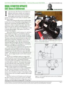
ELECTRICAL REBUILDER’S ASSOCIATION — Technical Document $S201904B www.electricalrebuilders.org DUAL STARTER UPDATE a CAT Does It Different e See n the last issue, Bob Thomas wrote about two different dual starter systems, one using two 50MT Delco starters to crank a locomotive’s diesel engine and another with two Bosch starters on a Komatsu truck with a 12 cylinder 4,000 HP diesel engine. While researching for that article, he told me that he had come across a Caterpillar wiring diagram for a dual starter system that was quite different, but no reference to when or where it was used. Since then, I performed a service call for a starting problem on a 2009 CAT 865C tractor with a CAT Challenger 15-liter 6 cylinder diesel engine. This tractor’s start circuit matched that diagram. This tractor had two nearly identical 12 volt Delco 42M starters (see Figure 1), mounted on opposite sides of the engine. The CAT part number for these starters is 198-7746, or Delco part number 104799294. The same system and starters are used on other CAT applications using their Challenger C15 or C18 (18- liters) diesel engines. Since they are mounted on opposite sides of the engine, the one on the left side requires re-clocking its DE housing prior to installation. start That is the only difference between the two. SWITCH Both starting systems explained in last month’s issue used a series circuit through the contacts of the drive engagement solenoids to activate the motor solenoids simultaneously only after both pinion gears were fully engaged. This required the use of two solenoids for each starter — one to engage the drive and the other to power the motor. But the CAT Challenger starters use single 42MT solenoids and the two are connected in parallel, powered by the same battery bank – four group 31 batteries connected together in parallel too. Each starter has its own IMS relay (see Figure 2). The tractor’s start circuit activates both IMS relays at the same time. Each IMS then activates its own starter solenoid, which in turn engages its drive and powers its starting motor. The possible problem of one starter cranking before the other clears an abutment is not addressed by this system. But evidently that has not been an issue. For as you can see in the photo (see Figure 3) the pinions of both of these starters were in excellent condition with no signs of milling. The Bosch system on the Komatsu was 24 volts and Figure 2 – CAT’s parallel dual starter system used on Challenger the Delco system on the locomotive used 32 volt 5|0MT C15 and C18 engines. starters. It could be that the lower voltage plays a part in allowing it to work without causing issues. At any rate, Figure 1 – This is pretty much a standard 42MT starter, except for the plastic cover for the terminals. STARTING MOTORS An ERA Publication. ©2019, Electrical Rebuilder’s Association. All rights reserved. No portion of the guide may be reproduced in Page 1 any way, or stored in any electronic retrieval system without the prior written consent of the Electrical Rebuilder’s Association. ELECTRICAL REBUILDER’S ASSOCIATION — Technical Document $S201904B www.electricalrebuilders.org DUAL STARTER UPDATE this CAT dual starter system works differently than those in last month’s issue and we thought you should be aware of it. While the starters were pretty much standard 42MT’s, the solenoid was unique, to accommodate the cover that you may have noticed in the photo. Obviously, Caterpillar did not want an operator to attempt emergency starting by manually jumping the terminals on the solenoid. The cover pretty much prevents any such actions. Figure 3 – As you can see from the original pinion gears, there is no sign of milling. Figure 4 – Here you can see the right side starter mounted on the engine. An ERA Publication. ©2019, Electrical Rebuilder’s Association. All rights reserved. No portion of the guide may be reproduced in Page 2 any way, or stored in any electronic retrieval system without the prior written consent of the Electrical Rebuilder’s Association.