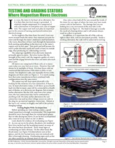
ELECTRICAL REBUILDER’S ASSOCIATION — Technical Document MS202003A www.electricalrebuilders.org TESTING AND GRADING STATORS Where Magnetism Moves Electrons na way, the stator is the heart of an alternator. For it is there that electrical energy is generated. A relatively simple component, it is comprised of only a lamination of steel plates and coils of copper wire. The copper and steel each play an important part in the process of turning mechanical motion into electrical energy. As the magnetic flux lines from the rotor’s iron core move around inside the stator, they emanate out past the rotor and through the stator’s stationary steel lamination. Like waves, these lines of force rush through the lamination, both pushing and pulling on the electrons in the stator’s copper coils as they pass. They push and pull because the rotor’s poles alternate north and south around its outside edge, thus producing AC (alternating current). The amperage capability of an alternator depends primarily upon its stator. But other factors like the strength of the rotor’s coil, the magnetic quality of rotor’s steel and the airgap between the rotor and stator also each play a part. All stators are comprised of three coils, or in many cases today you may find six or more. However they will always be in multiples of three. It is how those coils are connected that determines if the stator is delta or wye wound. For simplicity’s sake, our examples shown in the diagrams are three coils (see Figure 1). It is worth noting here that some manufacturers have combined both configurations into the same stator. The easiest way tell them apart physically is by looking for the existence of a wye connection, if there is one. In most alternators today, it will show up as a fourth lead wire that in many cases will be connected to a fourth pair of diodes, as is shown in our diagram. But on many earlier alternators like the 10SI, and even a few newer ones, the wye connection may not be connected to anything at all. On some earlier alternators the wye connection was used as a low voltage source or a pin in the plug for an external regulator connection. Output at the wye is AC current at roughly one half of the system’s charging voltage. Testing Begins With An Inspection Before spending any time testing a stator, a good visual inspection is strongly recommended. This inspection should be more thorough than the normal quick glance that we take during tear down. It can be best accomplished after removal of any caked on dirt or debris. Look closely for evidence of overheating (see Figure 2). As you can see in the photo, the plastic slot insulators have been melted and the insulating enamel on some of the wires has been discolored. These visual signs of overheating are fairly obvious. On the other hand, the Bosch stator (see Figure 3) looked almost new at first glance, and the few burned turns were not noticed until after a thorough cleaning. Overheating signs such as this are often caused by an internal short in one coil. “cei 8Y BOB THOMAS Also, take a close look all the way around the inside of the stator for any signs of where the rotor may have made contact with its lamination. The damage that you are looking for is any movement of the steel tabs in the lamination (see Figure 4). The kind of damage is usually the result of a bearing failure and it will almost always result in a short to ground. In addition, it is important that all of the coils are tight in their slots, with no movement possible. Inside a working alternator, the coils will be subjected to moving DIODES DIODES NEG NEG Pos CONNECTOR WYE-WOUND STATOR AND DIODES DELTA-WOUND STATOR AND DIODES Figure 2 – Overheated coil and melted insulators in Leece Neville stator. Figure 3 – Less obvious burned wires in a Bosch stator. An ERA Publication. ©2020, Electrical Rebuilder’s Association. All rights reserved. No portion of the guide may be reproduced in Page 1 any way, or stored in any electronic retrieval system without the prior written consent of the Electrical Rebuilder’s Association. ELECTRICAL REBUILDER’S ASSOCIATION — Technical Document MS202003A www.electricalrebuilders.org TESTING AND GRADING STATORS Figure 4 – Damaged lamination caused by rotor contact. Figure 5 – Working voltage for testing stators on this Ace E-2122 tester is only 6.8 volts. magnetic forces. While the copper itself cannot be directly affected by magnetism, the electrons inside the copper are. As the electrons are pushed and pulled back and forth inside the wire, the high frequency vibration is transferred to the wire itself. If there is any looseness, the vibrations will eventually rub through the insulation on the wire and result is an internally shorted coil. The coils were loose in the Bosch stator shown earlier. Testing for Short to Ground A short to ground sometimes referred to as a copper to steel short is just what it sounds like, a copper coil is making contact with the steel lamination at some point. Dead shorts can be easily detected using any low voltage source. My Ace E-2122 Alternator Analyzer (see Figure 5) uses 6.8 volts to test stators, which is only half the voltage of a 12-volt charging system. While this will reveal any dead short to ground, it will miss potential shorts that may eventually lead to a failure later under warranty. Potential shorts can be present when the insulation on the wire is beginning to break down or may have been damaged with few or no visible signs. Finding shorts of that type require a higher voltage source capable of jumping a small gap to ground in such trouble spots. One way to do this is to use what is called a “hi-pot” or “breakdown” tester. This type of equipment applies a much higher voltage than any alternator will ever experience, but at a controlled low level of current. The Slaughter Model 1101 in the photo (see Figure 6) can test at 250, 500 or 1,000 volts. It can be used to test for potential trouble spots in rotors or stators in alternators, as well as armatures, field coils and insulated brush holders in starters or generators. In last month’s issue, Mohammad Samii explained and demonstrated a simple hand-made tool capable of testing for shorts to ground. It’s been used in electrical rebuilding shops for around 100 years and utilizes a shop’s 120 volts AC power supply, a light bulb and two electrodes. Ice picks were the popular electrode choice when ice was the main source of refrigeration. As he pointed out in his column, these testers often reveal the location of the trouble spot visibly as sparks, smoke or sometimes both. Two words of caution whenever using any high voltage tools. First, there is an obvious danger of being careless around voltages that high. Under some conditions, they could cause injury or death. Rubber or plastic floor mats and a non-conductive work bench are recommended. A GFCI (ground fault circuit interrupt) breaker is recommended. The other is that carbon (brush dust) is conductive material, especially so at 120 volts, let alone at 1,000. Take the time to see exactly where the short is and what is causing it. Sometimes, these types of shorts can be cleaned and repaired, by filling the gap with a liquid filler like a penetrating epoxy. Most epoxies are good insulators to fill small gaps between bare metal parts. These higher voltage tools can pay for themselves quickly by saving you time in testing, reclaiming some parts that would have been replaced otherwise and reducing your number of warranties. Internal Shorts and Electrical Balance A stator can have an internal short without showing any of the visual signs of one. Balance testing is the easiest way to verify that none of the coils are internally shorted. An internal short is when there is copper to copper contact within one coil (between turns) or between two different coils where they overlap. Either one will change the resistance value of the shorted coil or coils and throw the stator out of electrical balance. To test for balance, voltage is applied to each coil (phase) of the stator, noting the amperage draw of that coil and then comparing the readings of all three coils. If there are no internal shorts, the amperage draw will be identical, or very close to it – allowing for slight variances due to resistance between the meter’s probes and the stator leads. If you have a copper to copper short within a single coil or between coils, you will see a clear difference as the shorted coil will have a lower resistance and therefore draw more amperage. BREAKDOWN OIELECTAIC BAB POSITIVE CO Figure 6 – Testing for a short to ground at 250 volts. An ERA Publication. ©2020, Electrical Rebuilder’s Association. All rights reserved. No portion of the guide may be reproduced in Page 2 any way, or stored in any electronic retrieval system without the prior written consent of the Electrical Rebuilder’s Association.